Download

1 / 15
291 likes | 1.32k Vues
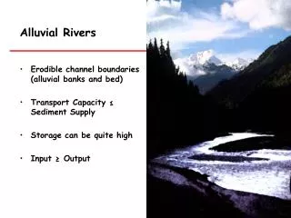
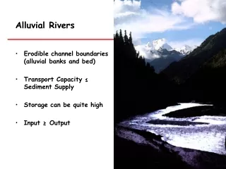
DESIGN OF ERODIBLE AND NON-ERODIBLE CHANNELS. According to Kennedy the critical velocity ratio Vc in a channel may be defined as the mean velocity of flow which will just keep the channel free from silting or scouring. His investigations pertain to Upper bari Doab canal in UP.

E N D
According to Kennedy the critical velocity ratio Vc in a channel may be defined as the mean velocity of flow which will just keep the channel free from silting or scouring. His investigations pertain to Upper bari Doab canal in UP. m = Critical velocity ratio = 1.1 to 1.2 for coarse sand = 0.8 to 0.9 for fine sand
Assume a depth of flow = d, m • Compute the critical velocity from kennady’s formula • Compute are of c/s of flow = Q/Vc • Assuming a side slope of channel, say 0.5:1 compute the bed width • Compute the wetted perimeter for the assumed depth abd computed bed width • Calculate C from Kutter’s formula and then the velocity of flow by Chezy’s equation • If the Velocity computed now is same as found by kennady’s method the design depth is correct • Otherwise repeat the above steps by assuming different depth of flow
He also defined critical velocity as non-silting –non-scouring velocity and gave a relation between critical velocities to the depth of flowing water.
The relation is, V0 = 0.55 D0.64 (OR V0 = 0.84 D0.64 in F.P.S Units In general V0 = CDn V0 = Critical velocity, in (m/s) D = Depth of water over bed portions of a channel in m n = any index number
The equation has been derived on the basis of observations on one canal only, it is applicable to only those channels, which are flowing, in sandy silt of the same quality or grade as that of Upper Bari Doab system.
Kennedy later realized the importance of silt grade on critical velocity and introduced a factor ‘m’ known as critical velocity ratio (C.V.R) in his equation. The equation is then written as V0 = 0.55 m D0.64 Where, m = C.V.R = V/ V0
Sand coarser than the standard was assigned value of m from 1.1 to 1.2 and those finer than the standard from 0.9 to 0.8. Generally, in a system of canal, higher C.V.R. is assumed in head reaches and lower value of C.V.R is assumed towards its tail end.
The value of constant C in equation for various grades of material may be assumed as follows:
Drawbacks in Kennedy’s theory • Kennedy did not notice importance of B/D ratio. • He aimed to find out only the average regime conditions for the design of a channel. • No account was taken of silt concentration and bed load, and the complex silt-carrying phenomenon was incorporated in a single factor m. • Silt grade and silt charge were not defined. • Kennedy did not give any slope equation. • Kennedy use kutter’s equation for the determination of mean velocity and therefore the limitations kutter’s equation got incorporated in Kennedy’s theory of channel design
THANK YOU PRESENTED BY PREETHA DEVI.R BTE-06-026