Regenerative Amplifier for Seeding Few Cycle Pulse Generation
10 likes | 195 Vues
Regenerative Amplifier for Seeding Few Cycle Pulse Generation Stephen Walker, Xiaoming Sun, Joseph Sanderson. COMPRESSION. MOTIVATION.

Regenerative Amplifier for Seeding Few Cycle Pulse Generation
E N D
Presentation Transcript
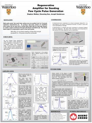
Regenerative Amplifier for Seeding Few Cycle Pulse Generation Stephen Walker, Xiaoming Sun, Joseph Sanderson COMPRESSION MOTIVATION A double prism pair compressor is a robust compressor design [5]. It is advantageous over grating compressors because it is easy to clean and not as susceptible to damage. A disadvantage of a double prism pair compressor is excessive residual third order dispersion. We utilize TOD mirrors [6] to pre-compensate for this residual third order dispersion before amplification. High peak power few-cycle laser pulses are an excellent tool for Coulomb explosion experiments [1]. To produce few-cycle pulses an amplified short pulse can be sent into a hollow fibre filled with an inert gas (argon) to create a super-continuum through self-phase modulation [2]. The broad band output is compressed to give a few-cycle pulse. With 40fs, 0.5 mJ pulses seeding a hollow fibre enough bandwidth for <7fs pulses should be achievable STRETCHING For any Chirped Pulse Amplification (CPA) [3] system careful tabulation of system dispersion is necessary in order to properly design the compression stage. A minimum amount of dispersion is also required before amplification to avoid damage to optical elements due to self focusing Preliminary results indicate that compressed pulse widths of <200fs have been achieved Each Component in the system adds a different amount of GVD and TOD Optimal system dispersion and amplified bandwidth should give ~40fs FWHM pulses with some residual third order and fourth order dispersion. FUTURE WORK AMPLIFICATION Active control of the phase of seed pulses entering the regenerative amplifier will be obtained by using a deformable mirror [7]. The deformable mirror can deliver a phase change of After the pulse stretcher the seeds spectral width is ~100nm FWHM. The GVD and TOD contributions from the stretcher components give a theoretical pulse width of ~1.5ps FWHM To a given wavelength, where Z is the mirror deflection. Ideally (not considering mirror bend radius) our mirror should be capable of a maximum GVD of ~3E+3 fs^2 or a TOD of ~2E+5 fs^3. In practice this is hard to achieve because the mirror does not take on an ideal shape. X Gain narrowing takes place due to the finite gain bandwidth of Ti:Saph. This effect can be quite severe for regenerative amplifiers where the seed makes many (~16) trips through the gain medium For a highly chirped pulse bandwidth and pulse length are proportional to each other. To avoid damage from self-focusing or undesirable non-linear phase shifts due to high pulse intensities it is desirable to keep the pulse width as wide as possible in the amplifier. The residual phase after compression is quite large outside of the window 750nm to 810nm. In order to obtain the shortest possible pulse we will seek to minimize phase in this region and contain our pulse bandwidth the aforementioned window. X To counteract the effect of gain narrowing a frequency dependent filter can be added to the amplifier cavity [4]. This technique is quite good at increasing bandwidth but it is lossy, decreasing the efficiency of the amplifier The amplified pulses out of our compressor will re-amplified in another multi-pass amplifier stage to increase the energy of our pulses from 500uJ to ~5mJ The re-amplified pulses will be used to seed few-cycle pulse generation in an argon filled hollow fibre. = The usual amplified bandwidth of pulses out of our regen is 50 to 65 nm FWHM. Narrower bandwidths can allow higher extraction efficiency. For a 50nm bandwidth we can extract ~500uJ from the amplifier REFERENCES FUNDING PROVIDED BY [1] F.Legare, PRA 71, 013415 (2005) [2] Nisoli et al. Appl Phys B 65, 189 (1997) [3] D. Strickland. Optics Communications 56, 219 (1985) [4] C.P.J Barty, Optics Letters 21, 219 (1995) [5] Z. Cheng, Optics Communications 201, 145 (2002) [6] Krausz et al. Optics Letters 20, 1397 (1995) [7] Optics Letters 24, 493 (1999) The measured pulse width indicates our B-Integral must be ~1 to 2 inside the amplifier