PWM Amplifier (Pulse Width Modulation)
PWM Amplifier (Pulse Width Modulation). …another application of Power Electronics. Power Affiliates Program - May 11, 2001 Robert Balog. University of Illinois at Urbana - Champaign. Classification of Amplifiers. Key difference. “Linear conduction”. “Switch action”. Conventional.

PWM Amplifier (Pulse Width Modulation)
E N D
Presentation Transcript
PWMAmplifier(Pulse Width Modulation) …another application ofPower Electronics Power Affiliates Program - May 11, 2001 Robert Balog University of Illinois at Urbana - Champaign
Key difference “Linear conduction” “Switch action” Conventional Switching
Device Ratings “Linear conduction” “Switch action” Conventional Switching
Motivation: • Class D switching output is highlyefficientcompared to the Class A or Class A/B amplifier. • Each switching device is eitherconducting currentorblocking voltage. Therefore the power dissipated in the device is zero. • Physically smaller (and cheaper) components can be used.
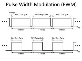
“buck” converter q(t) fixed duty ratio L & C Low Pass Filter or “average” Voutput is a constant “DC”
Can be a Full “H” Bridge or a Half Bridge Switch pairs (operate together): (1) SW1 & SW3 (2) SW2 & SW4 Note: if SW1 & SW4 are both closed, supply is shorted out. Dead Time circuit prevents this from occurring Typically there will be a low pass filter (LPF) before the load to filter out the high frequency carrier. In certain applications, the load may be inductive enough to act as the filter, for example, a motor.
Guarantees that only one pair of switches in on, preventing “shoot through” current typical of totem pole drive circuits.
Applications • Motor Drive • Servo Drive • Inverter power supply • Audio Amplifier
Demonstration: PWM Audio Amplifier
PWMAmplifier(Pulse Width Modulated) …another application ofPower Electronics Power Affiliates Program - May 11, 2001 Robert Balog University of Illinois at Urbana - Champaign