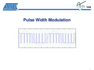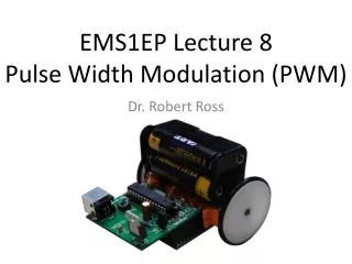
Pulse Width Modulation (PWM)
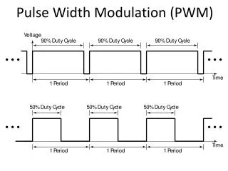
Pulse Width Modulation (PWM). Pulse Width Modulation (PWM). 100%. Pulse Width Modulation (PWM). 0%. On the chipKIT there are 490 periods per second. U se analogWrite (pin, value) to control the duty cycle on a pin. The value must be between 0 and 255.

Pulse Width Modulation (PWM)
E N D
Presentation Transcript
Pulse Width Modulation (PWM) 0% • On the chipKIT there are 490 periods per second. • Use analogWrite(pin, value) to controlthe duty cycle on a pin. • The value must be between 0 and 255. • The pin must be one of the underlined pins.
Pulse Width Modulation (PWM) • If you take the average value over one period,you can think of the voltage as being between0 V (0% duty cycle) and 3.3 V (100% duty cycle). • There are 256 different voltage levels (0 to 255).
Conversion of Analog to Digital • Obtain “analog” input using analogRead(). • analogRead()returns a value between 0 (if pin at ground) and 1023 (if pin at 3.3 V). • Argument of analogRead()is the pin to read(only pins labeled ANALOGIN can be used). • Used this to read setting of a potentiometer.
Pulse Width Modulation (PWM) Wrote led_with_potentiometer for this circuit.
Dimmable LED Program intpotPin = 0; // Pin for potentiometer. intledPin = 9; // Pin for LED. intpwmValue = 0; voidsetup() { Serial.begin(9600); // To see potentiometer setting. } voidloop() { // Read potentiometer value and set PWM value. pwmValue = analogRead(potPin) / 4; Serial.println(pwmValue, DEC); analogWrite(ledPin, pwmValue); // Set PWM duty cycle. delay(15); // Waits 15 ms. }
Transistor: Electrically Controlled Switch If “base” of the transistor is high, then current can flow freely.
Transistor: Electrically Controlled Switch If “base” of the transistor is low, then current cannot flow.