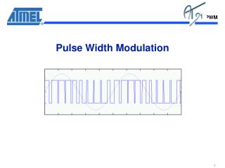
Pulse Width Modulation
Outline. IntroductionPWM DefinitionsGenerationTypesPWM on the HCS12Applications. 2. Presented by Zak Ahmad. Introduction. Pulse Width Modulation (PWM) is a technique for delivering partial power to a load via digital means.Other devices for delivering partial power: potentiometer and rheomete

Pulse Width Modulation
E N D
Presentation Transcript
1. Pulse Width Modulation By:
Zak Ahmad
Phuc Dao
Joel Toussaint
2. Outline Introduction
PWM Definitions
Generation
Types
PWM on the HCS12
Applications
2
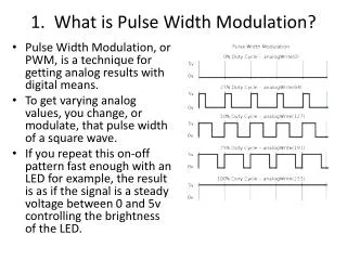
3. Introduction Pulse Width Modulation (PWM) is a technique for delivering partial power to a load via digital means.
Other devices for delivering partial power: potentiometer and rheometer.
3
4. Introduction Pulse Width Modulation (PWM) is a method for changing how long a square wave stays �on�.
The on-off behavior changes the average power of the signal.
If signal toggles between on and off quicker than the load, then the load is not affected by the toggling.
4
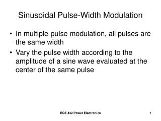
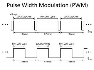
5. Duty Cycle - Introduction The duty cycle (the width of the signal) is modulated.
It is a percentage measurement of how long the signal stays on. 5
6. Duty Cycle - Definition 6
7. Advantages Average value proportional to duty cycle, D
Low power used in transistors used to switch the signal
Fast switching possible due to MOSFETS and power transistors at speeds in excess of 100 kHz
Digital signal is resistant to noise
Less heat dissipated versus using resistors for intermediate voltage values
7
8. Disadvantages Cost
Complexity of circuit
Radio Frequency Interference
Voltage spikes
Electromagnetic noise
8
9. PWM Generation - Analog Intersective Method 9
10. PWM Generation - Digital Delta Method 10
11. PWM Generation - Digital Delta Sigma Method 11
12. Types of PWM � Left Aligned Left edge is fixed, the trailing edge is modulated.
12
13. Types of PWM � Center Aligned Center of signal is fixed, both edges are modulated 13
14. Choosing PWM Frequency Application dependant.
Not too low:
Audible frequencies
Twice the inverse of device time constant
10 Times higher than control system frequency
Not too high:
Transistors generate more heat at higher frequencies
Some loads will not respond at higher frequencies 14
15. PWM You Tube Video You Tube search: PWM Tutorial
OR
Click Link 15
16. Outline Introduction
PWM Definitions
Generation
Types
PWM on the HCS12
Applications 16
17. Implementing PWM Using the MC9S12C32 17
18. PWM8B6C Module 18
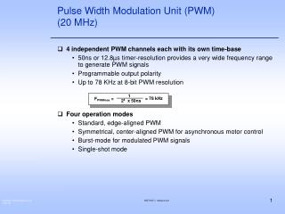
19. PWM8B6C Module - Other Features Four source clocks (A, B, SA, SB) for a wide frequency range
Emergency shutdown
Some changes take a complete cycle to take effect
Modes of Operation:
Normal: everything is available
Wait: Low-power consumption and clock disabled
Freeze: Option to disable input clock
20. PWM8B6C Memory Map
21. PWM Enable Register (PWME) PWME is located at $00E0
Set PWMEx
0: to disable PWM channel x
1: to enable PWM channel x
If 16-bit resolution is used, then PWME4/2/0 are disabled
22. PWM Polarity Register (PWMPOL) PWMPOL is located at $00E1
Set PPOLx to
0: output channel starts low and goes high when duty cycle is reached
1: output channel starts high and goes low when duty cycle is reached
23. PWM Clock Select Register (PWMCLK) PWMCLK is located at $00E2
Set PCLK5, PCLK4, PCLK1, PCLK0 to
0 to use Clock A
1 to use Clock SA
Set PCLK3, PCLK2 to
0 to use Clock B
1 to use Clock SB
24. PWM Prescaler Register (PWMPRCLK) PWMPRCLK is located at $00E3
Used to prescale clocks A and B
25. PWM Scale A Register (PWMSCLA) PWMSCLA is located at $00E8
Scale value used in scaling Clock A to generate Clock SA
Note: When PWMSCLA = $00, PWMSCLA value is considered a full scale value of 256.
26. PWMSCLB is located at $00E9
Scale value used in scaling Clock B to generate Clock SB
Note: When PWMSCLA = $00, PWMSCLA value is considered a full scale value of 256.
27. PWM Control Register (PWMCTL) PWMCTL is located at $00E5
Set CONxy to
0: to keep PWM channels separate (8-bit resolution)
1: to concatenate PWM channels x and y together (16-bit resolution)
Channel y determines the configuration
x becomes the high byte and y becomes the low byte
Bits PSWAI and PFRZ set either wait or freeze mode
Note: change these bits only when the corresponding channels are disabled
28. PWM Counter Register (PWMCNTx) Total of (6) 8-bit counters located at $00EC - $00F1
One up/down counter per channel
In left aligned mode, the counter counts from 0 to the value in the period register-1. In center aligned mode, the counter counts from zero to the value in the period register-1 and then back down to zero.
Any write to the register causes the value to be reset to #$00 and the counting procedure is restarted.
29. PWM Period Register (PWMPERx) (6) Period Registers located at $00F2 - $00F7
Determine the PWM period
Changes occur when:
Current period ends
Counter is written to
Channel is disabled
30. PWM Duty Register (PWMDTYx)
31. PWM Center Align Register (PWMCAE) PWMCAE is located at $00E4
Set CAEx to
0: for left align output signal
1: for center align output signal
Note: can only be set when channel is disabled
32. Left vs. Center Aligned Signal changes when counter is equal to period register
In the center aligned mode, the PWM counter goes from a down-count to a up-count to down-count, etc.
In the left aligned mode, the PWM counter is a up-counter and rests to zero when it overflows
33. 33
34. Outline Introduction
PWM Definitions
Generation
Types
PWM on the HCS12
Applications
34
35. Applications Telecommunications
DC motors
RC devices
Audio/video effects
Voltage regulation
Use as ADC
35
36. Telecommunications Used in communication since a digital signal is more robust and less vulnerable to noise.
Effective at data transmission over long distance transmission lines
The widths of the pulses correspond to specific data values encoded at one end and decoded at the other.
Pulses of various lengths (the information itself) will be sent at regular intervals (the carrier frequency of the modulation).
36
37. Application to DC Motors Voltage supplied is directly proportional to the duty cycle
Ability to control the speed of the motor via the duty cycle
Example
Can be used in regulating room temperature. A PC can sense the current temperature (using an analog-to-digital converter) and then automatically increase/decrease the fan's speed accordingly.
37
38. Transmitters send PWM signals to the receivers on board of Radio controlled devices for specific control.
38
39. Brightness controlled with a PWM circuit. 39
40. Video devices PWM dimming provides superior color quality in LED video display
With a 12 bits resolution
the TLC5940 PWM dimming can
provide up to 68.7 million colors
to a pixel.
40
41. Audio devices Used in audio amplifiers to generate output signals for cellphone speakers to high-power stereo systems
Produce less heat than traditional analog amplifiers
Saving energy. Critical for hand held electronics.
Gives a sound effect similar to chorus when used in audio circuit.
41
42. Power delivery effective at data transmission over long distance transmission line
Power transfer: PWM used to reduce the total power given to a load without relying on resistive losses
42
43. Using PWM to generate an analog voltage level Any shape waveform can be created
PWM frequency should be much higher than the frequency of waveform generated
43
44. Example of PWM circuit with 555 timer 44
45. Reference http://cp.literature.agilent.com/litweb/pdf/5988-9904EN.pdf
http://www.robotroom.com/PWM4.html
MC9S12C Family, MC9S12GC Family Reference Manual, (pp. 347-382)
ME 4447/6405 PWM Student Lectures
www.wikipedia.org
Han-Way Huang, The HCS12/9S12: An Introduction to Software & Hardware Interfacing. Thomson Delmar Learning, United States. 2006.
http://www.pcmag.com/encyclopedia_term/0,2542,t=PWM&i=49992,00.asp
http://www.ece.tamu.edu/~reddy/ee449/notes/pulse.pdf
http://cp.literature.agilent.com/litweb/pdf/5988-9904EN.pdf
http://homepages.which.net/~paul.hills/SpeedControl/SpeedControllersBody.html
45