Sinusoidal Pulse-Width Modulation
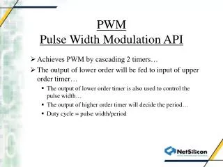
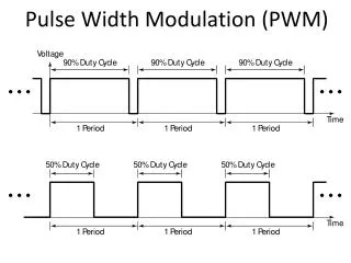
Sinusoidal Pulse-Width Modulation. In multiple-pulse modulation, all pulses are the same width Vary the pulse width according to the amplitude of a sine wave evaluated at the center of the same pulse. Generate the gating signal. 2 Reference Signals, v r , -v r.

Sinusoidal Pulse-Width Modulation
E N D
Presentation Transcript
Sinusoidal Pulse-Width Modulation • In multiple-pulse modulation, all pulses are the same width • Vary the pulse width according to the amplitude of a sine wave evaluated at the center of the same pulse ECE 442 Power Electronics
Generate the gating signal 2 Reference Signals, vr, -vr ECE 442 Power Electronics
Comparing the carrier and reference signals • Generate g1 signal by comparison with vr • Generate g4 signal by comparison with -vr ECE 442 Power Electronics
Comparing the carrier and reference signals ECE 442 Power Electronics
Potential problem if Q1 and Q4 try to turn ON at the same time! ECE 442 Power Electronics
If we prevent the problem Output voltage is low when g1 and g4 are both high ECE 442 Power Electronics
This composite signal is difficult to generate ECE 442 Power Electronics
Generate the same gate pulses with one sine wave ECE 442 Power Electronics
Alternate scheme ECE 442 Power Electronics
rms output voltage • Depends on the modulation index, M Where δm is the width of the mth pulse ECE 442 Power Electronics
Fourier coefficients of the output voltage ECE 442 Power Electronics
Harmonic Profile ECE 442 Power Electronics
Compare with multiple-pulse case for p=5 Distortion Factor is considerably less ECE 442 Power Electronics