Lecture 06: Memory Address Decoding
Lecture 06: Memory Address Decoding. The 80x86 IBM PC and Compatible Computers. Chapter 10 Memory and Memory Interfacing Chapter 11 I/O and the 8255. Terms about Memory - Revisit. Capacity: how many bits that a memory module contains E.g., 64M (bits)


Lecture 06: Memory Address Decoding
E N D
Presentation Transcript
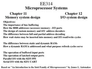
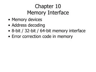
The 80x86 IBM PC and Compatible Computers Chapter 10 Memory and Memory Interfacing Chapter 11 I/O and the 8255
Terms about Memory - Revisit • Capacity: how many bits that a memory module contains • E.g., 64M (bits) • Organization: how many bits can be accessed simultaneously (a memory unit, memory word) & thus how many words of a memory module • E.g., 64M X 1, 16M X 4, 8M X 8 • 2a X d • Access time: how long does it take from putting the address on the address pins to getting the data from the data pins
Memory Address Decoding • According to your instructions that access memory • E.g., MOV AX, [0012H] • CPU calculates the physical address and put corresponding signals on the address bus • E.g., if DS=0900H, what’s the PA? • Memory address decoding circuitry locates the specific memory chip that stores the desired data • Examine address decoding using logic gates and 74LS138 decoder chips
Memory Address Decoding PA of 0900:0012 = 09012H
Quiz What’s the address range?
Using 74LS138 to Decode Grounded
Quiz 2 What’s the address range for Y4 and Y7?
More on Address Decoding • Absolute address decoding • All address lines are decoded • Linear select decoding • Only selected lines are decoded • Cheap • But with aliases: the same memory unit (I/O port) with multiple addresses • Why this happens?
Example 1. In a particular computer, the address range from 0000h to 3FFFh is used for ROM, the range from 4000h to 5FFFh is reserved for future use, and the range from 6000h to0FFFFh is used for RAM. Assume that the control signals for RAM are CS~ and WE~, and the CPU has 16 address pins (i.e., A15~A0), 8 data pins (i.e., D7~D0), and R/W~ and MREQ~ control signals. Achieve the following requests.(1) draw the address decoding solution using a 74LS138 chip(2) if both ROM and RAM are built with 8K×1 memory chips, try to draw the connection between the CPU and the memory.(3) if ROM is built with 8K×8memory chips and RAM is built with 4K×8 chips, try to draw the connection between the CPU and the memory.(4) what if ROMis built with 16K×8memory chips and RAM is built with 8K×8memory chips?
(1) draw the address decoding solution using a 74LS138 chip Solution.
(2) if both ROM and RAM are built with 8K×1 memory chips, try to draw the connection between the CPU and the memory. Solution.
(3) if ROM is built with 8K×8memory chips and RAM is built with 4K×8 chips, try to draw the connection between the CPU and the memory. Solution.
(4) what if ROMis built with 16K×8memory chips and RAM is built with 8K×8memory chips? Solution.
Example 2. Assume one computer system needs 512 byte RAM and 512 byte ROM. If RAM is built with 128×8 memory chips and ROM is built with 512×8 memory chips, please specify the address range of each memory chip. Given that RAM chips need CS~and WE~ control signals, ROM chips need only CS~ control signal, and the CPU has 16 address pins (A15~A0), 8 data pins (D7~D0) and R/W~ and MREQ~ control signals, draw the connection between the CPU and the memory. Solution. The address range of each memory chip:
WE A CS A CS WE A CS WE A CS WE A CS 512x8 128x8 128x8 128x8 128x8 D7~D0 D7~D0 D7~D0 D7~D0 D7~D0 As the total volume of the memory is 1K, we need 10 address lines. RAM chips need 7 address lines and ROM chips need 10 address lines. MREQ# A7A8A9 3-8 decoder OE# & A15~A0 A6~A0 R/W# A8~A0 CPU D7~D0
Data Integrity • Checksum byte for ROM • Parity bit for DRAM • CRC for disks and the Internet
Checksum Byte • Check the integrity of a series of bytes • Calculation • Add all bytes together and drop all carries • Take the 2’s complement of the sum • Store the checksum byte together with data • check the integrity by adding data and the checksum together • Then how to prove the integrity of the data? • E.g., 38H, 23H, 33H, 07H, what is the checksum byte? 6BH
Parity bit • Check the integrity of a series of bits (a byte) • Calculation • If even number of 1s, the bit is set
Memory Organization in 8086 • Even and odd banks
Byte-Memory Operations • Byte-memory operation at even address X MOV AL, [100h] • Byte-memory operation at odd address X+1 • MOV AL, [101h]
Aligned Word-Memory Operations • Accessing an aligned word at even address X MOV AX, [100h]
Misaligned Word-Memory Operations • Accessing an misaligned wordat odd address X+1 MOV AX, [101h]
I/O in X86 family – The Other Space from Memory • X86 microprocessors have an I/O space in addition to memory space • Use special I/O instructions accessing I/O devices at ports (i.e., addresses for I/O) • Memory can contain machine codes and data, I/O ports only contain data • Also referred to as peripheral I/Oor isolated I/O
I/O Instructions – 8-Bit Instance • Direct I/O instructions: • port# ranges from 00h to 0ffh, 256 ports in total • Indirect I/O instructions: • port# ranges from 0000h to 0ffffh, 65536 ports in all • use a 16-bit address that resides in the DX register • Note: no segment concept for port addresses
I/O Example ‘Y’
Output Port Design • Latch the data coming from the CPU • Address decoding What is the address of this port?
Input Port Design • Use tri-state buffer to connect to system data bus • Address decoding What is the address of this port?