Download
1 / 46
460 likes | 572 Vues
This document delves into Thevenin’s and Norton’s Theorems, two essential tools for simplifying circuit analysis. These theorems enable the conversion of complex circuits into simpler equivalent circuits, enhancing focus on key components like amplifiers and speakers. Learn how to apply source transformations and analyze circuits effectively, reducing distortion and ensuring optimal performance. Through practical examples and techniques, you will develop a robust understanding of these powerful theorems and their applications in electrical engineering.

E N D
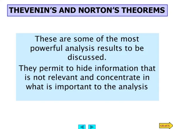
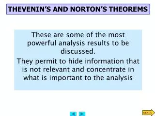
THEVENIN’S AND NORTON’S THEOREMS These are some of the most powerful analysis results to be discussed. They permit to hide information that is not relevant and concentrate in what is important to the analysis
From PreAmp (voltage ) To speakers REPLACE AMPLIFIER BY SIMPLER “EQUIVALENT” TO MATCH SPEAKERS AND AMPLIFIER IT IS MUCH EASIER TO CONSIDER THIS EQUIVALENT CIRCUIT! Low distortion audio power amplifier TO MATCH SPEAKERS AND AMPLIFIER ONE SHOULD ANALYZE THIS CIRCUIT Courtesy of M.J. Renardson http://angelfire.com/ab3/mjramp/index.html
Thevenin Equivalent Circuit for PART A THEVENIN’S EQUIVALENCE THEOREM
Norton Equivalent Circuit for PART A NORTON’S EQUIVALENCE THEOREM
All independent sources set to zero in A OUTLINE OF PROOF - version 1 If Circuit A is unchanged then the current should be the same FOR ANY Vo USE SOURCE SUPERPOSITION HOW DO WE INTERPRET THIS RESULT?
1. Because of the linearity of the models, for any Part B the relationship between Vo and the current, i, has to be of the form 3. If part B is an open circuit then i=0 and... OUTLINE OF PROOF - version 2 2. Result must hold for “every valid Part B” that we can imagine 4. If Part B is a short circuit then Vo is zero. In this case How do we interpret this?
For ANY circuit in Part B The voltage source is called the THEVENIN EQUIVALENT SOURCE The resistance is called the THEVENIN EQUIVALENT RESISTANCE PART A MUST BEHAVE LIKE THIS CIRCUIT THEVENIN APPROACH This is the Thevenin equivalent circuit for the circuit in Part A
Norton Norton Approach
Thevenin Norton ANOTHER VIEW OF THEVENIN’S AND NORTON’S THEOREMS This equivalence can be viewed as a source transformation problem It shows how to convert a voltage source in series with a resistor into an equivalent current source in parallel with the resistor SOURCE TRANSFORMATION CAN BE A GOOD TOOL TO REDUCE THE COMPLEXITY OF A CIRCUIT
Source Transformationcan be used to determine the Thevenin or Norton Equivalent... BUT THERE MAY BE MORE EFFICIENT TECHNIQUES Source transformation is a good tool to reduce complexity in a circuit ... WHEN IT CAN BE APPLIED!! “ideal sources” are not good models for real behavior of sources A real battery does not produce infinite current when short-circuited
EXAMPLE: SOLVE BY SOURCE TRANSFORMATION In between the terminals we connect a current source and a resistance in parallel The equivalent current source will have the value 12V/3k The 3k and the 6k resistors now are in parallel and can be combined In between the terminals we connect a voltage source in series with the resistor The equivalent source has value 4mA*2k The 2k and the 2k resistor become connected in series and can be combined After the transformation the sources can be combined The equivalent current source has value 8V/4k and the combined current source has value 4mA Options at this point 1. Do another source transformation and get a single loop circuit 2. Use current divider to compute I_0 and then compute V_0 using Ohm’s law
EQUIVALENT CIRCUITS Or one more source transformation 3 current sources in parallel and three resistors in parallel PROBLEM Compute V_0 using source transformation
Source Transformationcan be used to determine the Thevenin or Norton Equivalent... WE NOW REVIEW SEVERAL EFFICIENT APPROACHES TO DETERMINE THEVENIN OR NORTON EQUIVALENT CIRCUITS RECAP OF SOURCE TRANSFORMATION
One circuit problem 1. Determine the Thevenin equivalent source Remove part B and compute the OPEN CIRCUIT voltage Second circuit problem Remove part B and compute the SHORT CIRCUIT current 2. Determine the SHORT CIRCUIT current A General Procedure to Determine the Thevenin Equivalent
NODE ANALYSIS When the current source is open the current through the short circuit is When the voltage source is set to zero, the current through the short circuit is To compute the Thevenin resistance we use Is this a general result? For this case the Thevenin resistance can be computed as the resistance from a - b when all independent sources have been set to zero AN EXAMPLE OF DETERMINING THE THEVENIN EQUIVALENT Part B is irrelevant. The voltage V_ab will be the value of the Thevenin equivalent source. What is an efficient technique to compute the open circuit voltage? Now for the short circuit current Lets try source superposition
“Part B” “Part B” Determining the Thevenin Equivalent in Circuits with Only INDEPENDENT SOURCES The Thevenin Equivalent Source is computed as the open loop voltage The Thevenin Equivalent Resistance CAN BE COMPUTED by setting to zero all the sources and then determining the resistance seen from the terminals where the equivalent will be placed Since the evaluation of the Thevenin equivalent can be very simple, we can add it to our toolkit for the solution of circuits!!
“PART B” LEARNING BY DOING
LEARNING EXAMPLE COMPUTE Vo USING THEVENIN For open loop voltage use KVL In the region shown, one could use source transformation twice and reduce that part to a single source with a resistor. ... Or we can apply Thevenin Equivalence to that part (viewed as “Part A”) For the open loop voltage the part outside the region is eliminated The original circuit becomes... And one can apply Thevenin one more time! ...and we have a simple voltage divider!!
For the Thevenin resistance “Part B” Or we can use Thevenin only once to get a voltage divider Contribution of the voltage source Contribution of the current source For the Thevenin voltage we have to analyze the following circuit METHOD?? Source superposition, for example Thevenin Equivalent of “Part A” Simple Voltage Divider
“Part B” LEARNING EXAMPLE USE THEVENIN TO COMPUTE Vo You have the choice on the way to partition the circuit. Make “Part A” as simple as possible Since there are only independent sources, for the Thevenin resistance we set to zero all sources and determine the equivalent resistance For the open circuit voltage we analyze the following circuit (“Part A”) ... The circuit becomes...
“PART B” RESULTING EQUIVALENT CIRCUIT LEARNING EXTENSION: USE THEVENIN TO COMPUTE Vo
PART B PART B LEARNING EXTENSION: COMPUTE Vo USING NORTON COMPUTE Vo USING THEVENIN
SAMPLE PROBLEM KVL Opening the current source: Short circuiting the voltage source This is what we need to get KVL Equivalent Resistance: Independent sources only Equivalent Voltage: Node, loop, superposition… Do loops How about source superposition?
,,, An to compute Equivalent Source... SOURCE TRANSFORMATION SAMPLE PROLEM All independent sources All resistors are in parallel!! The circuit can be simplified Voltage divider
(actually that statement has to be qualified a bit. What happens if ) FOR ANY PROPERLY DESIGNED CICUIT WITH ONLY DEPENDENT SOURCES This is a big simplification!! But we need a special approach for the computation of the Thevenin equivalent resistance THEVENIN EQUIVALENT FOR CIRCUITS WITH ONLY DEPENDENT SOURCES A circuit with only dependent sources cannot self start. Since the circuit cannot self start we need to probe it with an external source The source can be either a voltage source or a current source and its value can be chosen arbitrarily! Which one to choose is often determined by the simplicity of the resulting circuit
IF WE CHOOSE A VOLTAGE PROBE... WE MUST COMPUTE CURRENT SUPPLIED BY PROBE SOURCE The value chosen for the probe voltage is irrelevant. Oftentimes we simply set it to one
IF WE CHOOSE A CURRENT SOURCE PROBE We must compute the node voltage V_p The value of the probe current is irrelevant. For simplicity it is often choosen as one.
Controlling variable: Using voltage probe. Must compute current supplied LEARNING EXAMPLE FIND THE THEVENIN EQUIVALENT Do we use current probe or voltage probe? If we use voltage probe there is only one node not connected through source
LEARNING EXAMPLE Find the Thevenin Equivalent circuit at A - B Controlling variable Thevenin equivalent Only dependent sources. Hence V_th = 0 To compute the equivalent resistance we must apply an external probe We choose to apply a current probe @V_1 @V_2 “Conventional” circuit with dependent sources - use node analysis
SAMPLE PROBLEM Thevenin equivalent The resistance is numerically equal to V_p but with units of KOhm Loop analysis Controlling variable Voltage across current probe
Thevenin EquivalentCircuits with both Dependent and Independent Sources We will compute open circuit voltage and short circuit current For each determination of a Thevenin equivalent we will solve two circuits Any and all the techniques discussed should be readily available; e.g., KCL, KVL,combination series/parallel, node, loop analysis, source superposition, source transformation, homogeneity The approach of setting to zero all sources and then combining resistances to determine the Thevenin resistance is in general not applicable!!
Guidelines to partition: “Part B” EXAMPLE Use Thevenin to determine Vo “Part A” should be as simple as possible. After “Part A” is replaced by the Thevenin equivalent we should have a very simple circuit The dependent sources and their controlling variables must remain together Constraint at super node Open circuit voltage Options??? KCL at super node Equation for controlling variable Solve Short circuit current Negative resistances for some “a’s” Solution to the problem Setting all sources to zero and combining resistances will yield an incorrect value!!!!
Find Vo using Thevenin Super node KVL Open circuit voltage Controlling variable KVL Method??? Short Circuit Current The equivalent circuit KCL The equivalent resistance cannot be obtained by short circuiting the sources and determining the resistance of the resulting interconnection of resistors
EXAMPLE: Use Thevenin to compute Vo “Part B” KVL for V_oc Same as before Thevenin resistance DON’T PANIC!! Select your partition Now compute V_0 using the Thevenin equivalent Use loops Open Circuit Voltage Loop equations Controlling variable Loop equations Short circuit current Controlling variable
The alternative for mixed sources Open circuit voltage Short circuit current Equivalent Resistance EXAMPLE
SAMPLE PROBLEM supernode Open circuit voltage KCL at super node KCL at supernode KVL Mixed sources. Must compute Voc and Isc The two 4k resistors are in parallel Short circuit current FINAL ANSWER
SAMPLE PROBLEM Single node FINAL ANSWER Mixed sources! Must compute open loop voltage and short circuit current Open circuit voltage For Vx use voltage divider For Vb use KVL Short circuit current We need to compute V_x KCL@Vx KCL again can give the short circuit current
LEARNING EXAMPLE DATA TO BE PLOTTED Using EXCEL to generate and plot data
LEARNING EXAMPLE DATA TO BE PLOTTED Using MATLAB to generate and plot data » Rx=[0:0.1:10]'; %define the range of resistors to use » Voc=12-6*Rx./(Rx+4); %the formula for Voc. Notice "./" » Rth=4*Rx./(4+Rx); %formula for Thevenin resistance. » plot(Rx,Voc,'bo', Rx,Rth,'md') » title('USING MATLAB'), %proper graphing tools » grid, xlabel('Rx(kOhm)'), ylabel('Volts/kOhms') » legend('Voc[V]','Rth[kOhm]')
USUAL INTERPRETATION Thevenin A MORE GENERAL VIEW OF THEVENIN THEOREM THIS INTERPRETATION APPLIES EVEN WHEN THE PASSIVE ELEMENTS INCLUDE INDUCTORS AND CAPACITORS
From PreAmp (voltage ) To speakers BASIC MODEL FOR THE ANALYSIS OF POWER TRANSFER MAXIMUM POWER TRANSFER Courtesy of M.J. Renardson http://angelfire.com/ab3/mjramp/index.html The simplest model for a speaker is a resistance...
3 MAXIMUM POWER TRANSFER For every choice of R_L we have a different power. How do we find the maximum value? Consider P_L as a function of R_L and find the maximum of such function Set the derivative to zero to find extreme points. For this case we need to set to zero the numerator Technically we need to verify that it is indeed a maximum The maximum power transfer theorem The value of the maximum power that can be transferred is The load that maximizes the power transfer for a circuit is equal to the Thevenin equivalent resistance of the circuit. ONLY IN THIS CASE WE NEED TO COMPUTE THE THEVENIN VOLTAGE
LEARNING EXAMPLE a We need to find the Thevenin resistance at a - b. b Resistance for maximum power transfer The circuit contains only independent sources .... If we MUST find the value of the power that can be transferred THEN we need the Thevenin voltage!!!
a 1. Find the Thevenin equivalent at a - b c 2. Remember that for maximum power transfer b d .... And it is simpler if we do Thevenin at c - d and account for the 4k at the end Controlling variable: LEARNING EXAMPLE This is a mixed sources problem Now the short circuit current Remember now where the partition was made