Download
1 / 30
300 likes | 551 Vues
Noise sources at high frequency in Virgo E. Tournefier (LAPP-CNRS) ILAS WG1 meeting, Hannover December 12 th ,2005. Recycled ITF sensitivities Noise sources phase noise frequency noise environmental noise laser noises Summary. Recycled locking scheme. Laser.

E N D
Noise sources at high frequency in VirgoE. Tournefier(LAPP-CNRS)ILAS WG1 meeting, HannoverDecember 12th ,2005 • Recycled ITF sensitivities • Noise sources • phase noise • frequency noise • environmental noise • laser noises • Summary
Recycled locking scheme Laser • B1_ACp -> Arms differential mode • B5_ACq -> Small Michelson differential mode • B5_ACp -> Arms common mode (frequency stabilisation) • B2_3f_ACp -> Recycling cavity length + Recycling mirror Beam Splitter - 0 B5 B2_3f phase B1 phase Differential Mode control loop B5 quad SSFS B5 phase
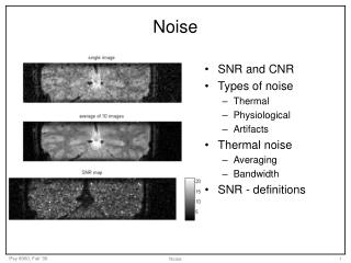
Recycled ITF sensitivities • Input power on ITF: ~ 1 Watt • C5 run: 5-7 Dec. 2004 • no automatic alignment • C6 run: 29 Jul – 12 Aug 2005 • partial automatic alignment • C7 run: 14-18 Sep 2005 • automatic alignment on 5 mirrors (NE, WE, NI, BS, PR) • ‘hierarchical’ control • modulation index: 0.16 -> 0.3 C5 sensitivity C6 sensitivity ~25 W on BS C7 sensitivity Virgo design (500 W on BS)
C5 sensititivy C5 recycled sensitivity B1 Electronic noise B1 Shot noise Phase noise ( model with = 0.45 rad/(Hz)) ~ x 30 • At high frequencies: C5 sensitivity ~ 30 times higher than B1 shot + electronic noise => it was explained with phase noise
Phase noise? • Observation: At high frequency, the noise is proportionnal to the signal amplitude on the other quadrature of B1:B1_ACp = x B1_ACqrms B1_ACp mean noise at high frequency B1_ACq integrated RMS
Phase noise 6 MHz EOM LO board ACp = x ACq Signal arriving on the photodiode: S= Sp + Sq = sp cos (t) + sq sin(t) where =2fmod Demodulation process: ‘multiplies’ S by the oscillator (LO) signal: LO=cos (t+0) ACp = S x LO0 = (sp cos (t) + sq sin(t)) x cos (t) = sp/2 +…(0 = 0) ACq = S x LO90 = (sp cos (t) + sq sin(t)) x sin (t) = sq/2 +… (0 = 90) If there is phase noise : LO = cos (t + + 0) then: ACp = (sp cos (t) + sq sin(t+ )) x cos (t) = (sp+ sq) /2 + … • ACp contains phase noise proportionally to the ACq level. Estimation of with the C5 data: = ACp noise / ACq total rms <=> ~ 0.4 rad/Hz
LO board phase noise 6 MHz EOM LO board ACp = x ACq • Measurement of the phase noise introduced by the LO board • LO ~ 0.3 rad/Hz • there are 2 LO boards used in cascade • B1 ~ 2 x LO = 0.45 rad/Hz this corresponds to the phase noise observed during C5 • C5 sensitivity is limited by LO board phase noise • Improvement of LO board: • board contains: • phase shifter • splitter 1 -> 8 outputs • amplitude loop to keep output level constant • noise comes from the ‘amplitude loop’ • removed (was not absolutely needed) • noise well decreased: LO < 0.1 rad/Hz
Oscillator phase noise 6 MHz gen EOM genx TFIMC gen Marconi (gen) = genx (1-TFIMC) After demod. () • Oscillator (6MHz) phase noise: gen • Filtered through IMC => does not cancel in the demodulation process: = genx (1-TFIMC) • Oscillator used up to now: Marconi generator ~ qq 0.1 rad/Hz => might be too high for Virgo • Replaced by LNFS-100 during this autumn shutdown => expected phase noise: < 0.03 rad/Hz
Phase noise: from C5 to C6 C5 C6 • Two possibilities to reduce the impact of phase noise: B1_ACp = x B1_ACqrms 1/ reduce the phase noise at the source (generator / LO board) 2/reduce the amplitude of the signal on the other quadrature: B1_ACq 1/ New LO board => reduced by at least 3 2/ Partial linear alignment during C6 => ACq signal reduced by ~ 20 to 50 ! • phase noise expected to be reduced by at least 150 for C6 !
From C5 to C6 Phase noise reduction thanks to: • Automatic alignment => reduced ACq signal • Improved LO board => C6 sensitivity is not limited by phase noise C5 sensitivity C5 phase noise (from LO board) C6 sensitivity C6 phase noise (from Marconi)
C6 noise budget • C6 (high frequency) sensitivity is limited by: - frequency noise (dominant) - shot and electronic noise to a smaller extent
B5 B5 d2 d2 C6 frequency noise 25 % 80 % d1 d1 25 % 10 % 10 % 50 % 2f 2f to SSFS Laser / x L x CMRR B5_ACp B1_ACp Laser frequency control loop (SSFS) B5 shot noise (and electronic noise): areseen by the frequency stabilisation loop (SSFS) and introduced in the ITF as frequency noise => frequency noise on B1_ACp: / x L x CMRR CMRR = common mode rejection ratio To reduce this effect: - optimise the shot noise on the photodiode used for the SSFS: * use most of B5 beam on this photodiode * increase the modulation depth => larger signal but same shot noise - improve the CMRR (alignment, symmetry of the arm defects) done between C6 and C7
C7 noise budget • Frequency noise /~2 ~ lower than B1 shot noise • B5 shot noise reduced ~ /2 • modulation index x 2 • but CMRR was slightly worse (B5 shot noise) Estimated freq. noise for Virgo design (500 Watts on BS): => frequency noise should still be reduced => will need to improve CMRR
Environmental noise • Seismic / acoustic noise couples to the optical benches (laser and detection labs) Environmental noise in detection lab: Vacuum pump (600Hz) on detection tower => harmonics + structures at ~ 2 kHz • will better isolate the detection bench from the pump vibrations Vacuum pump ON Vacuum pump OFF
Environmental noise P r laser Environmental noise in laser lab (acoustic, seismic) => beam jitter (r , ) => converted into power noise (P ) and frequency noise () by IMC Power noise (P/P ) couples to dark fringe proportionally to the locking accuracy (Lrms ): L = Lrms x P/P Frequency noise ()couples through the common mode rejection ratio: L/L = CMRR x / P/P + / + with: = r/w0 , = /0 L P/P , /
Power noise during C6 (1/2) B1_ACp L x P/P Power noise (P/P ) couples to dark fringe proportionally to the locking accuracy (Lrms ): L = Lrms x P/P Power noise projection using Lrms = 2.10-12 m (realistic value) => Power noise explains well the structures between 200 Hz and 1 kHz during C6 coherence between P noise and B1_ACp
Power noise during C6 (2/2) Power after IMC Old P stab New P stab P laser Sensitivity • Improvement of the power stabilisation at the end of C6 run r P stab • Good improvement of the sensitivity in the 200 Hz – 1kHz region • Power noise should not limit the final Virgo sensitivity
C7 environmental noise IB pump OFF • Many structures above 400 Hz • They disappear when the pumps of the Input Bench tower are switched OFF • What are they? • power noise? was well reduced during C6 • It should not be • frequency noise?
Environmental noise during C7 Freq noise IB_tx error signal • IB Pumps ON • IB Pumps OFF Coherences with B1_ACp • Structures above 400 Hz look like frequency noise • Foreseen improvements: - better isolation from environmental noise - better alignment control - improved frequency stabilisation?
Summary of C5, C6 and C7 noises • C5 : • dominated by phase noise • reduced (/~100) with automatic alignment + LO board improvement • next: new generator (Marconi -> LNFS-100) <- done • C6 : • > 1kHz dominated by frequency noise(B5 shot noise) • reduced (/2) with more beam on B5 photodiode + increased modulation index • 200 – 1kHz : power noise(from environmental noise) • reduced (/10-100) with improved power stabilisation • C7 : • > 1kHz: mixture of B1 shot noise + frequency noise (B5 shot noise) • next: - more power (new input bench) - improved CMRR • 200 – 1kHz: frequency noise (from environmental noise) • next: better isolation of the input bench + improved CMRR
Summary of C5, C6 and C7 noises Extrapolation of B1 shot noise + frequency noise (B5 s.n.) for 500 W on BS C5 sensitivity C6 sensitivity 25 W on BS C7 sensitivity Virgo design (500 W on BS) What else between C7 and Virgo design?
Power incident on BS: can we reach 500 Watts? If losses reduced by 2: Px1.25 => PBS~ 440 W • Power incident on BS before shutdown: • Incident power on PR: P0 = 0.8 -1 W • Recycling gain (all modes) R = 31 • Beam matching ~ 94% • Expected at the restart: • Incident power on PR: P0 = 8 -10 W • Recycling gain (new PR: 92 -> 95%) R00 = 43 • Negligible mismatching PBS = 25 W R00 = 33 PBS ~ 350 W • Are there possibilities to increase the input power? • Laser power = 22 Watts, but more than 50% is lost between laser and PR • Losses: • 25% on laser benches • 17% due to mismatching • 30% due to IMC losses • new optics / cleaning ? • can be improved with better alignment • new IMC mirrors
What about laser technical noise at 6 MHz ? • Laser technical power noise at 6 MHz couples to B1_ACp: B1_ACp = 2xP/P x PB1_DC (Note: a good contrast is important) • C7: laser noise : B1_ACp= 2 x 1.5 10-9 x 4.5 mW =1 10-11 W/Hz B1 shot noise : ~ 6 10-11 W/ Hz => not seen in C7 • PBS = 500 Watts: (=> ~ 100 mW on B1) laser noise : 19 10-11 W/Hz B1 shot noise: 27 10-11 W/ Hz • A pre-mode cleaner will be installed to reduce the laser technical noise => P/P ~ 1.5 10-9 Hz @ 6.26 MHz
Conclusion • Identified noises at high frequency and foreseen improvements: • Phase noise • better generator (+ improved electronics?) • Frequency noise (injected by the frequency stabilisation) • better rejection of the common mode • Environmental noise => power noise and frequency noise • better acoustic/seismic isolation of the benches • Laser technical noise (not yet observed) • Pre-mode cleaner • Shot noise: • Increase input power / recycling gain • …?
C7 noise budget: high frequency floor • Noise sources above ~ 300 Hz: estimated contribution @ 1 kHz - B1 electronic noise 2.6 x 10⁻²² - B1 shot noise 4.1 x 10⁻²² - B5 shot noise (frequency noise) 4.3 x 10⁻²² - Phase noise (6MHz oscillator: Marconi) 2.6 x 10⁻²² - Laser power noise at the 6MHz 0.7 x 10⁻²² 7. 10-22 /Hz (design: 7.2 10-23) Scaling of noises with the power incident on BS: For PBS x n - elec noise / n - shot noise / n - phase & power noise: idem After shutdown, expect n > 10 => Phase and laser power noises become important
C7 noise budget below 200 Hz (1/2) • Below 50 Hz: mixture of most of the correction signals • Above 50 Hz: - NI & PR ty (error signal originates from the same quadrant photodiode) - WI ty up to ~ 200 Hz ! • Coherences with the angular correction signals: WI NI NE PR BS WE
B1 shot noise • The shot noise limited sensitivity depends on: • the contrast defect: 1-C ~ 5 10-5 (B1) and 1-C ~ 5 10-4 (B1p) • the modulation depth: m=0.16 until C6 , m=0.3 for C7 • the transmission of the sidebands: T ~ 0.15 (design: T=0.4) • the recycling gain: R=30 • The contrast defect on B1 is good: It should allow to reach the optimum sensitivity for m=0.2-0.3 Shot noise limited sensitivity m=0.16 ~B1p B1
CMRR and frequency noise 0.15 % • The CMRR is given by the asymmetry of the two arms: • finesse asymmetry • losses asymmetry • and the quality of the alignment • Simulation result (R. Gouaty) for F/F=4% and round trip loss asymmetry=200ppm CMRR dominated by loss asymmetry => In good alignment conditions the simulated CMRR explains well the measured sensitivity Sensitivity from Aug 27 B1 electronic noise B1 shot noise Simulated frequency noise (B5 sn) SIESTA Simulation
CMRR C6 (12 Aug) (drift control) Aug 27th (4 LA loops + drift control) Aug 31st (10 LA loops) Evolution of the CMRR (arbitrary units) with LA configuration: • The CMRR is less stable (37mHz,…) but can reach smaller values with 10 LA loops • The net effect is a higher frequency noise Possible to tune the LA + damp 37mHz in order to keep a small CMRR?
PMC Mechanical Vacuum tank 74mm Mirror glued on piezo actuator Zerodur Front mirrors Spider 126mm mirror Corundum ½ sphere Glued mirrors piezo Brewster window 0.35m • Triangular zerodur cavity • * avoid thermal control & provide low mechanical Q • Controlled by 1 piezo • * Corundum half sphere glued on piezo • * Pushing a “telescope spider” shaped like support • * 6mm thick/12mm diam mirror, glued on spider • -> Avoid piezo bending transfer to mirror displacement) • ( simulation by F. Richard) • Vacuum tank, Brewster window