Download
1 / 20
220 likes | 1.03k Vues
Explore the definition, origins, and types of noise in signal processing, ranging from extrinsic sources like RF interference to intrinsic sources like thermal and shot noise. Learn about circuit representations and noise characteristics in amplifying systems.

E N D
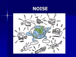
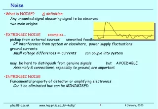
What is NOISE? A definition: Any unwanted signal obscuring signal to be observed two main origins EXTRINSIC NOISE examples... pickup from external sources unwanted feedback RF interference from system or elsewhere, power supply fluctuations ground currents small voltage differences => currents can couple into system may be hard to distinguish from genuine signals but AVOIDABLE Assembly & connections, especially to ground, are important INTRINSIC NOISE Fundamental property of detector or amplifying electronics Can’t be eliminated but can be MINIMISED Noise g.hall@ic.ac.uk www.hep.ph.ic.ac.uk/~hallg/
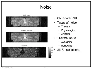
1. Thermal noise Quantum-statistical phenomenon Charge carriers in constant thermal motion macroscopic fluctuations in electrical state of system 2. Shot noise Random fluctuations in DC current flow originates in quantisation of charge non-continuous current 3. 1/f noise Characteristic of many physical systems least well understood noise source commonly associated with interface states in MOS electronics Origins of noise in amplifying systems g.hall@ic.ac.uk www.hep.ph.ic.ac.uk/~hallg/
Einstein (1906) , Johnson, Nyquist (1928) Mean voltage <v> = 0 Variance <v2> = 4kT.R.∆f ∆f = observing bandwidth s(v) = √<v2> = 1.3 10-10 (R.∆f)1/2 volts at 300K e.g. R = 1MΩ ∆f= 1Hz s(v) = 0.13µV Noise power = 4kT.∆f independent of R & q independent of f - WHITE Circuit representations Noise generator + noiseless resistance R Spectral densities mean square noise voltage or current per unit frequency interval wV(f) = 4kTR (voltage) wI(f) = 4kT/R (current) Thermal noise gaussian distribution of fluctuations in v g.hall@ic.ac.uk www.hep.ph.ic.ac.uk/~hallg/
Poisson fluctuations of charge carrier number eg arrival of charges at electrode in system - induce charges on electrode quantised in amplitude and time Examples electrons/holes crossing potential barrier in diode or transistor electron flow in vacuum tube < in2> = 2qI.∆f WHITE (NB notation e = q) I = DC current Shot noise gaussian distribution of fluctuations in i g.hall@ic.ac.uk www.hep.ph.ic.ac.uk/~hallg/
White noise sources frequently dominate in many real systems however frequency dependent noise is also common 1/f noise is a generic term for a wide range of phenomena, possibly not always related Power spectral density w(f) = Af/fn n ~ 0.8-1.5 typical Most important for MOS FET devices, often dominates but can also arise in other circumstances e.g. dielectrics,… 1/f noise pMOS transistor noise spectrum g.hall@ic.ac.uk www.hep.ph.ic.ac.uk/~hallg/
Most amplifying systems designed to be linear S(t) = S1(t) + S2(t) +S3(t) + … Impulse response h(t) = response to d Transfer function H(w) = vout(w)/vin(w) = ∫-∞∞ h(t).e-jw t dt ie impulse response h(t) and transfer function H(w) are Fourier pair In a linear system, if random impulses occur at rate n average response <v> = n ∫-∞tobs h(t)dt variance s2 = n∫-∞tobs [h2(t)]dt so s2 = n ∫-∞∞ h2(t) dt = n∫-∞∞|H(w)|2 df Campbell’s theorem i.e. sum all pulses preceding time, tobs, of observation g.hall@ic.ac.uk www.hep.ph.ic.ac.uk/~hallg/
typical application - precise measurements of x-ray or gamma-ray energies pre-amplifier first stage of amplification main amplifier - adds gain and provides bandwidth limiting ADC - analogue to digital conversion - signal amplitude to binary number fast amplifier and logic - start ADC ("gate") and flag interesting "events" to DAQ system - most signals arrive randomly in time. Other logic required to maximise chance of "good" event, eg second detector Amplifier systems for spectroscopy g.hall@ic.ac.uk www.hep.ph.ic.ac.uk/~hallg/
Combine uncorrelated noise sources in quadrature e2tot = e12 +e22 +e32 + … + in2R2 +... follows from Campbell's theorem consider as combinations of gaussian distributions First stage of amplifier dominates noise originates at input input transistor is most important - defines noise in most cases Noise is independent of amplifier gain or input impedance so noise can be referred to input In real systems both are approximations - but normally good ones so often sufficient to focus on input device "Rules" of low noise amplifier systems g.hall@ic.ac.uk www.hep.ph.ic.ac.uk/~hallg/
Amplifier systems (and amplifiers!) usually consist of several stages impractical to put all gain at one location - power, heating, material, size,... Calculate signal and noise at output Sout = G1.G2.G3Sin for 3 stage system, but can easily extend to N (eout)2= G12.G22.G32e12+ G22.G32e22+ G32e32 (eout /Sout)2= (e12 + e22/G12+ e32/G12.G22)/Sin2 Desirable to maximise gain at input stage eg stage 1 boosts signal enough for transmission down cable and should be large enough that environmental noise is not significant Amplifiers - dominance of input stage g.hall@ic.ac.uk www.hep.ph.ic.ac.uk/~hallg/
Normal to partition noise sources not fundamental to calculations but can simplify! Parallel noise sources appear as currents at input detector leakage current bias resistors feedback resistor … Amplifiers - location of noise sources • Series noise sources appear as voltage at input • transistor gate noise • device series resistance • microstrip or transistor • load resistor in amplifier • ... g.hall@ic.ac.uk www.hep.ph.ic.ac.uk/~hallg/
noise at output Eno2 = A2 {e2nZ2in/(Zin + Rs)2 + i2nR2sZ2in/(Zin + Rs)2 } transfer function K = Vout/Vin = A.Vsig.Zin /(Zin + Rs)Vsig = AZin/(Zin + Rs) noise at input Eni2= Eno2/K2 => E2ni = e2n + i2nR2sno Zin or A dependence easy to show analogous result I2ni = i2n + e2n/R2s choice is for convenience in most detector systems, there is a current signal source and a parallel capacitance then the spectral distribution of noise at the input is affected I2ni = i2n + e2nw2C2no longer white Amplifiers - reference to input assume: signal source and associated impedance noise sources amplifier with gain & input impedance g.hall@ic.ac.uk www.hep.ph.ic.ac.uk/~hallg/
Current sensitive - common for photodiode signals vout ≈ -iinRf signals follow input current, ie fast response but not lowest noise Charge sensitive amplifier Ideally, simple integrator with Cf but need means to discharge capacitor - large Rf Simple integrator vout ≈ -Q/Cf with feedback resistor Rf vout(t) ≈ -(Q/Cf)exp(-t/t) t = Rf Cf Preamplifier types g.hall@ic.ac.uk www.hep.ph.ic.ac.uk/~hallg/
Knowing Noise sources Amplifier components and basic design How to achieve “best” signal to noise? Possible constraints power consumption layout of system (space, cables,…) signal rate eg. signal "pileup" vs E resolution Two methods Pulse shaping time invariant filter Pulse sampling time variant filter Signal processing g.hall@ic.ac.uk www.hep.ph.ic.ac.uk/~hallg/
General result is ENC2 = aen2 C2/t + b in2t + gC2 a,b depend on pulse shape calculate in t or f g : 1/f - can be computed in f only a minimum noise can be achieved with a given shaping time constant chosen depending on magnitudes of noise sources Useful point of comparison: CR-RC bandpass filter Noise after pulse shaping only 36% worse than theoretical optimal filter g.hall@ic.ac.uk www.hep.ph.ic.ac.uk/~hallg/
ENC = signal which produces output amplitude equal to r.m.s. noise Noise must be compared with known signal to calibrate system How to inject an impulse of known size? Equivalent Noise Charge • desirable to measure in absolute units - e, coul, keV(Si),.. Qtest = CtestVtest = Ne measure Vout for known Qtest g.hall@ic.ac.uk www.hep.ph.ic.ac.uk/~hallg/
An approximate numerical value using CR-RC filter, ignoring 1/f noise ie I = 1nA t = 1µs ENCp ≈ 100e Rs = 10Ω C = 10pF t = 1µs ENCs ≈ 24e Some numerical values g.hall@ic.ac.uk www.hep.ph.ic.ac.uk/~hallg/
Alternative to pulse shaping filters based on summation Sample & hold method initially switches S0 B1 B2 open, S1 S2 closed switch S0 is Reset Vout = output from charge sensitive preamplifier open S1 : preserves Vout on C1 after time ∆t open S2 : preserves Vout on C2 then, close B1 and B2: output A = V1 - V2 reset preamp later need to know when signal will arrive! Switched capacitor easy to implement convenient for MOS technology Vout Time variant filters g.hall@ic.ac.uk www.hep.ph.ic.ac.uk/~hallg/
Integrate signal during application of gate - another time variant filter convert charge to digital number = convolution of pulse shape with gate so w(t) = h(t) * ggate(t) (ignoring t reflection) Tgate << t Tgate >> t Integrating Analogue to Digital Converter (ADC) Tgate = 5t w(t) = h(t) new, wider weighting function can change filtering and increase or decrease noise g.hall@ic.ac.uk www.hep.ph.ic.ac.uk/~hallg/
Eventually need to convert signal to a number quantisation (rounding) of number = noise source the more precise the digitisation, the smaller the noise After digitisation all that is known is that signal was between -∆/2 and ∆/2 <x> = ∫x.p(x).dx/∫p(x).dx s2 = <x2> = ∫x2.p(x).dx /∫p(x).dx ∫p(x).dx = ∫-∆/2∆/2 dx = [x] -∆/2∆/2 = ∆ ∫x2.p(x).dx = ∫-∆/2∆/2 x2.dx = [x3/3] -∆/2∆/2 = 2∆3/24 so s2 = ∆2/12 ie statistical noise which is proportional to digitisation unit Digitisation noise g.hall@ic.ac.uk www.hep.ph.ic.ac.uk/~hallg/
When did signal cross threshold ? noise causes “jitter” Dt = snoise/(dV/dt) compromise between bandwidth (increased dV/dt) noise (decreased bandwidth) limits systems where preamplifier pulse used to generate trigger eg x-ray detection typical preamp response V = Vmax(1-e-t/trise) so ∆t ≈ snoisetrise/ Vmax t << t Time measurements and noise g.hall@ic.ac.uk www.hep.ph.ic.ac.uk/~hallg/