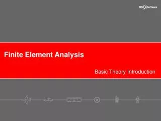
Finite Elements Analysis Basics
This guide explores the fundamentals of Finite Element Analysis (FEA) in the design of gear shafts and valves. Key quantities examined in gear shaft design include stress, strain, displacement, rotation, and temperature. For valves and heat sinks, we evaluate pressure drop, temperature, mass flow rate, fluid velocity, and mixing. The guide emphasizes the necessity of breaking complex geometries into simpler elements for accurate analysis, detailing mesh size variations to optimize computation time and accuracy. Key analysis steps from geometry definition to result evaluation are highlighted.


Finite Elements Analysis Basics
E N D
Presentation Transcript
Analysis Foundation In designing the gear shafts below, what quantities would we examine? • Stress • Strain • Displacement • Rotation • Temperatures
Analysis Foundation In designing a valve, burner, or heat sink, what quantities would we examine? • Pressure drop • Temperatures • Mass flow rate • Velocities • Fluid mixing
Hand calculations are easily applied to simple geometries. Cylinders Blocks Beam structures They are not easily or accurately applied to general (complex) shapes. Analysis Foundation To analyze complex shapes we break them into many simple shapes and compute the combined response.
FEA Analogy: Area Suppose we want to compute the area of a generic shape.
FEA Analogy: Area What do we do to improve the accuracy of the area measurement?
FEA Mesh The pieces we divide the model into are called ELEMENTS. Equations are generated for each element. These are combined into a system of equations for the entire structure. Matrix algebra is used to solve the system of equations.
FEA Mesh: Elements • Each element is a simple solid. • Elements are connected together at locations called NODES.
Analysis Accuracy • Fewer elements will solve more quickly. • More elements will be more accurate. You need to strike a balance between model size and run time.
Accuracy vs Mesh Size Moderate Mesh: 7009 nodes Fine Mesh: 16,107 nodes Coarse Mesh: 1773 nodes
Accuracy vs Mesh Size Coarse Mesh: 1773 nodes Moderate Mesh: 7009 nodes Fine Mesh: 16,107 nodes Sol. Time: 5 sec. Max. Stress: 27.8 ksi Sol. Time: 10 sec. Max. Stress: 27.6 ksi Sol. Time: 2 sec. Max. Stress: 25.8 ksi
Mesh Transition • Many times different locations in the model do not require the same accuracy. • Use mesh control and transition capabilities to focus the computational effort in the areas where the most accuracy is required.
Modify, Update, Refine (Design Analysis) Design Analysis Steps • Geometry definition. • Define component materials. • Define physical situation with boundary conditions. • Mesh the model. • Run the analysis (solve the system of equations). • View and evaluate the results.