Download
1 / 19
190 likes | 312 Vues
How to convert high-speed images of a welding arc in to time-resolved 2D temperature profiles. IIW 2014 Seoul SG212 "Physics of Welding“ Gregor Gött DirkUhrlandt. Overview. Motivation Set-up Filter Optical system Electronic system Emission coefficient Method I Method II

E N D
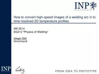
How to convert high-speed images of a welding arc in to time-resolved 2D temperature profiles IIW 2014 Seoul SG212 "Physics of Welding“ Gregor Gött DirkUhrlandt
Overview Motivation Set-up Filter Optical system Electronic system Emission coefficient Method I Method II Calibration or not? Summary 15000 12000 9000 6000 3000 T(K) G. Gött, IIW 2014 Seoul (SG212), July 14th 2014
Motivation • Spectroscopic analysis of arcs is widely used • Gives accurate results • 1D spectra • Spectral selective high-speed imaging gives 2D-T (temperature) profiles which result in a better understanding of the arc structure • High repetition rate G. Gött, IIW 2014 Seoul (SG212), July 14th 2014
Set-up Object MIF Lens CCD Metal-Interference Filter or Monochromator N:\Projekte\2012\2012_DD9198-Sp_AiF-Gase\03_Publications(Veröffentlichungen)\201407-IIW-Seoul\Vortrag\Abbildungen\Sceme-Setup\All.svg G. Gött, IIW 2014 Seoul (SG212), July 14th 2014
Purpose of the Filter N:\Projekte\2012\2012_DD9198-Sp_AiF-Gase\03_Publications(Veröffentlichungen)\201407-IIW-Seoul\Vortrag\Abbildungen\Spectrum.opj G. Gött, IIW 2014 Seoul (SG212), July 14th 2014
Purpose of the Filter (Metal-Interference Filter) Filter transmits only Ar-atom lines Metal lines from the overexposed core-region are blocked N:\Intern\OptischeFilter\Metallinterferenzfilter\Filterkurven_E56_Gött-Kozakov\MIF811_488.opj G. Gött, IIW 2014 Seoul (SG212), July 14th 2014
Effect of the optical system Object MIF Lens CCD Each individual pixel represents a sensor with no inherent spatial resolution… …but combined pixel give a spatial information G. Gött, IIW 2014 Seoul (SG212), July 14th 2014
Calculating the emission-coefficient e(r) cylindrical symmetric arc measured: spectral radiance [W m-2 nm-1 sr-1 ] Abel-transformation e(r) calculated: emission-coefficient e(r) L(y) G. Gött, IIW 2014 Seoul (SG212), July 14th 2014
Calculating the emission-coefficient e(r) Method I:Fitting of L(y) by aproximating and transforming e(r) with a spline Abel-transformation Method II:Separating the arc in pixel sized annuli (concentric circular rings) and calculating the e(r) recursively from the outside to the inside G. Gött, IIW 2014 Seoul (SG212), July 14th 2014
Calculating the emission-coefficient e(r) In Method I the disturbance at the center (material transfer blocks the view) will also influence the regions outside. In case of disturbed arc Method II does not underestimate the maximum and it only effects the region where it occurs. G. Gött, IIW 2014 Seoul (SG212), July 14th 2014
Calculating the emission-coefficient e(r) cylindrical symmetric arc measured: spectral radiance [W m-2 nm-1 sr-1 ] Abel-transformation e(r) calculated: emission-coefficient e(r) L(y) G. Gött, IIW 2014 Seoul (SG212), July 14th 2014
Calculating the emission-coefficient e(r) cylindrical symmetric arc measured: spectral radiance [W m-2 nm-1 sr-1 ] Abel-transformation e(r) e(r) calculated: emission-coefficient e(r) L(y) L(y) G. Gött, IIW 2014 Seoul (SG212), July 14th 2014
Correlation e(r) and nu emission-coefficient radiator density Knowing the composition and atomic data T can be obtained from nu (one spectral line) Measurement must be absolutely calibrated G. Gött, IIW 2014 Seoul (SG212), July 14th 2014
Calibration Object MIF Lens CCD Readout RAW or don’t touch Image processor G. Gött, IIW 2014 Seoul (SG212), July 14th 2014
e(r) to T(r) 15000 12000 9000 6000 3000 T(K) Calculation for emission-coefficients below the norm maximum Finding the Normmaximum with a reference process G. Gött, IIW 2014 Seoul (SG212), July 14th 2014
Calibration with a TIG-Process 15000 Ar II - Line 12000 9000 6000 3000 T(K) N:\Projekte\2012\2012_DD9198-Sp_AiF-Gase\03_Publications(Veröffentlichungen)\201407-IIW-Seoul\Vortrag\Berechnungen\TIG\T No absolute calibration necessary but a reference process with significant ion radiation N:\Projekte\2012\2012_DD9198-Sp_AiF-Gase\03_Publications(Veröffentlichungen)\201407-IIW-Seoul\Vortrag\Berechnungen\ Adaptation of the Fowler-Milne method G. Gött, IIW 2014 Seoul (SG212), July 14th 2014
Summary • Points to consider: • sdf G. Gött, IIW 2014 Seoul (SG212), July 14th 2014
Contact Leibniz Institute for Plasma Science and Technology Address: Felix-Hausdorff-Str. 217489 Greifswald Phone: +49 - 3834 - 554 300 Fax: +49 - 3834 - 554 301 E-Mail: g.goett@inp-greifswald.deWeb: www.inp-greifswald.de Work funded by the AiF (IGF-No. 17.431B) G. Gött, IIW 2014 Seoul (SG212), July 14th 2014