Embedded Profile Control | Unico
The Embedded Profile Control system is a scalable motion control system designed specifically for metal forming applications. It provides coordinated motion control for up to 20 drives in as many as 20 independent axes in its standard configuration.<br><br>Read more: https://bit.ly/3GS2ufr

Embedded Profile Control | Unico
E N D
Presentation Transcript
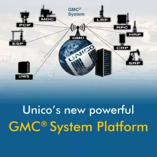
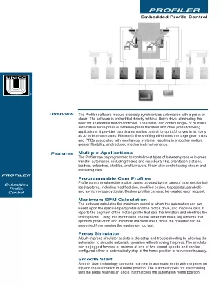
PROFILER Embedded Profile Control ® Overview The Profiler software module precisely synchronizes automation with a press or shear. The software is embedded directly within a Unico drive, eliminating the need for an external motion controller. The Profiler can control single- or multiaxis automation for in-press or between-press transfers and other press-following applications. It provides coordinated motion control for up to 32 drives in as many as 32 independent axes. Electronic line shafting eliminates the large gear boxes and PTOs associated with mechanical systems, resulting in smoother motion, greater flexibility, and reduced mechanical maintenance. Multiple Applications The Profiler can be programmed to control most types of between-press or in-press transfer automation, including tri-axis and crossbar STFs, orientation stations, loaders, unloaders, shuttles, and turnovers. It can also control swing shears and oscillating dies. Features PROFILER Programmable Cam Profiles Profile control emulates the motion curves provided by the cams of most mechanical feed systems, including modified sine, modified cosine, trapezoidal, parabolic, and asynchronous cycloidal. Custom profiles can also be created upon request. Embedded Profile Control Maximum SPM Calculation The software calculates the maximum speed at which the automation can run based upon the specified part profile and the motor, drive, and machine data. It reports the segment of the motion profile that sets the limitation and identifies the limiting factor. Using this information, the die setter can make adjustments that optimize production and minimize machine wear, while the operator can be prevented from running the equipment too fast. Press Simulator A built-in press simulator assists in die setup and troubleshooting by allowing the automation to simulate automatic operation without moving the press. The simulator can be jogged forward or reverse at one of two preset speeds and can be configured either to automatically stop at the home position or to run continuously. Smooth Start Smooth Start technology starts the machine in automatic mode with the press on top and the automation in a home position. The automation will not start moving until the press reaches an angle that matches the automation home position.
Embedded Profile Control PROFILER Features (continued) Smooth Stop With Smooth Stop technology, the automation continues moving smoothly to its home position while the press stops on top during a cycle stop. Smooth Return Smooth Return technology smoothes operation by insulating the automation from the vibration and mechanical backlash of the press. The control dynamically switches between following the press and following an internal simulator for a portion of every stroke. The simulator is synchronized to the speed and position of the press during the transition, and press position is continually monitored to ensure that the simulator does not fall behind. Smooth Transfer Using Smooth Transfer technology, the drive switches from following one press to another on the fly using an optimal trajectory to compensate for differences in the velocity and position of the two presses. The automation leaves the first press at a designated safe point then follows a simulated press angle that is generated to match the velocity and position of the second press within the specified press angle window. The automation then starts following the second press. Programmable Limit Switches An advanced Programmable Limit Switch (PLS) controller provides contact outputs that turn on and off based on the position of the press, automation, or both. These outputs can be used to control grippers, vacuum cups, die lifters, oil sprays, and part tracking windows. Each PLS output has independent speed compensation to ensure, for example, that grippers will open and close in the same place regardless of press speed. Off-Path Jog Each axis controlled by the Profiler may be jogged individually without moving the other axes or the press. The control can be configured to limit off-path motion to the limits of the programmed motion path or to the mechanical travel limits. Position, velocity, and acceleration of a profiling axis versus press angle for different cam types Subtle differences in velocity and acceleration can make a significant difference in the RMS or peak current required of the drive, the peak velocity required by the motor, and the G-forces exerted on the mechanics and object being transferred Go-To Positions and Angles As many as four go-to positions and four go-to angles can be configured for each drive. For each go-to position, the user specifies where the axis will move to, how fast it will move, and how much torque may be used during the move. These go-to positions can then be selected with digital I/O to send the automation to the preprogrammed positions. This is particularly useful for sequencing an automatic die-change routine. Go-to angles similarly send the simulator to preprogrammed positions that all synchronized drives will follow. Multiple Referencing Schemes The Profiler supports snug-up (positive stop) referencing, limit-switch referencing, and learn/teach referencing. The drive does not need to be re-referenced every time the machine is powered down if at least one of its feedback devices is an absolute encoder. Referencing is only required if the encoder is replaced or its coupling is loosened. Multiple Motor Types The controller supports any combination of motors, including AC induction, brushless or permanent-magnet AC synchronous, and wound-field or permanent- magnet DC motors. Common Bus Architecture Profiler drive systems use a common-bus architecture that allows multiple drives to be tied together and share a single line-regenerative or non-regenerative front end. The result is a more streamlined design that greatly reduces peak energy demands.
Features (continued) Event-Driven Data Logging A built-in data logger can record any drive parameter or any analog, digital, or serial I/O data within the drive. Multiple channels of data can be grouped into a channel set, and multiple channel sets can be configured. Each channel and channel set can be sampled at different sample rates. Sampling can be continuous or triggered by complex user-defined trigger conditions. Captured data can be read and displayed by an HMI in real time, subject to limits of the serial connection, or buffered in the drive for subsequent retrieval and analysis. An optional memory expansion module is also available that allows multiple sample sets to be stored on a removable SD memory card. Program Extensibility The control can be customized to a specific installation using UEdit™, a powerful Windows-based programming tool that lets users add their own ladder logic and function-block programming. Multilevel Protection Multiple levels of protection are employed to ensure operator and machine safety. The drive detects numerous fault conditions such as RMS and peak overcurrent, overtemperature, encoder loss, and power supply failure. The application detects such conditions as feedback mismatch, twist between motors on the same axis, press or simulator following errors, and communication errors. Safety Features Redundant Feedback The Profiler supports redundant feedback for the press crank angle encoder as well as for each drive/motor. If the system detects a problem with its primary feedback device, it can automatically switch to the redundant encoder, flag a fault, and bring the machine to a safe, controlled stop. Zone Control Multiple fault-handling zones allow drives to respond differently to certain faults depending on the mode of operation and the position of the press. Slave Takeover Should the master drive fail on an axis that has one or more torque slaves, the system can be configured to enable one of the slave drives to assume control to bring the axis to a controlled stop. PLC Interface The Profiler is designed to interface with a line-control PLC via a serial link and/or digital I/O. The serial link is used for transmitting and receiving diagnostic information and job-specific part data. Digital I/O are used for sending and receiving control and status bits (for example, to jog the automation or to indicate that the automation is ready to follow the press). If a high-speed protocol is used for the serial link, it is possible to send the control and status bits serially and eliminate the digital I/O. Supported protocols include: • ControlNet™ • Modbus®Plus • AnyBus®S-Slave • EtherCAT • Modbus®TCP • Profibus • Ethernet IP PROFILER Embedded Profile Control
Embedded Profile Control PROFILER Inputs/ Outputs The Profiler has numerous control and status bits that can be mapped by the user to digital or serial I/O within the drive. Each drive supports up to 36 optically isolated digital I/O points that are directly connected to the drive and can be individually configured as inputs or outputs. As many as 32 additional optically isolated digital I/O points can be connected through an OptoMux®serial gateway. Each drive also supports up to four 16-bit serial I/O input words, four 16-bit serial output words, four serial ADC words, and four serial DAC words when using most high-speed protocols. The control and status bits that can be mapped to these I/O bits include: Control Bits • motor on • fault reset • press mode • simulator mode • jog simulator forward • jog simulator reverse • jog forward • jog reverse • synchronize • desynchronize • home simulator • snug-up • go to position 1 • go to position 2 • go to position 3 • go to position 4 • store • press running • jog fast • stop at home • return with simulator • stop with simulator Status Bits • motor on granted • no faults • press selected • simulator selected • synchronized • simulator at home • at position 1 • at position 2 • at position 3 • at position 4 • at storage • auto selected • E-stop request • cycle stop request • simulator moving forward • simulator moving reverse • press enable • press at top • axis straight • snug-up complete • part data OK • drive moving p t d u t All trade designations are provided without reference to the rights of their respective owners. a x Specifications subject to change without notice. Unico is a leading global innovator of motion-control solutions for industry. Founded in 1967, the company develops, manufactures, and services variable-speed drives, application-engineered drive products, integrated drive systems, and ancillary products that improve operations by increasing productivity, safety, and equipment life while lowering energy and maintenance costs. 2000.21(022) 5/20