Download
1 / 31
360 likes | 997 Vues
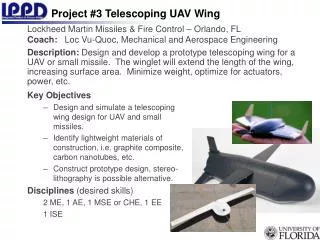
Aerospace Structures and Materials: Wing Design (Asymmetric Box Beam Analysis). Dr. Tom Dragone Orbital Sciences Corporation. Motivation. By the end of this lecture, you will have all the analysis tools needed to determine stresses and shear flows in virtually any wing structure... Questions:

E N D
Aerospace Structures and Materials:Wing Design (Asymmetric Box Beam Analysis) Dr. Tom Dragone Orbital Sciences Corporation
Motivation • By the end of this lecture, you will have all the analysis tools needed to determine stresses and shear flows in virtually any wing structure... Questions: • What are the primary functions of wing structure? I.e. What must it do? • What are the most important internal loads for a wing? • Would a beam make a good wing? Would a thin plate make a good wing? • What is the most efficient way to make a wing?
Wing Design / Analysis • Wing analysis is similar to fuselage analysis • Same process, but a different geometry FUSELAGE WING
Single Cell, Multiple Stringer Box Beam Process (Transport Wing) • Idealize structure into stringers and webs • Calculate section properties at 2 sections • CG, I, etc • Usually neglect self-inertias • Find stringer axial stress at each section from • For fuselage, symmetry => Ixy = 0 • For wing, often no symmetry • Find “cut-web” shear flows for shear applied to shear center • Find “torque-balancing” shear flow for applied torsion • Add “cut-web” and “torque-balancing” shear flows for total
P1 P2 P3 1 3 2 5 6 4 P6 P5 P4 Mx z y x Single Cell, Multiple StringerBox Beam Process BENDING LOADS
V V T qo12 q12 qo23 q23 qo61 =0 q61 qo56 qo45 qo34 q56 q45 q34 qo qt qi Set by DP2 Set by DP1 q q q Set by DP3 n1 12 23 34 ... n1 12 23 34 ... n1 12 23 34 ... Single Cell, Multiple StringerBox Beam Process SHEAR FLOWS qt = + = +
P2 qn qn+1 Dx P1 x Cut-Web Shear Flows Change in Load on a Stringer Between 2 Sections Determines the Change in Shear Flow Across the Stringer => Must Calculate A, CG, I, s, and P at Each of the 2 Sections
+ + = CCW LOAD SENSE MAGNITUDE SHEAR FLOW Tensile Compressive Cut-Web Shear Flow Sense SIGN CONVENTION
q12 q23 q61 q56 q45 q34 Indeterminate Structure • With n-1 equations in n unknowns, can solve for 1 variable in terms of the n-1 others • Need another equation => Use torsion equilibrium • Assume 1 shear flow is zero => I.e. cut the web • Get cut web shear flows in other webs • Usually choose qn1=0 n Equations . . . n-1 Independent Equations
Torsional Shear Flow • What is the torsional moment caused by a shear flow in a skin? h q L t AEnclosed = Lh/2
A12 A23 qo12 qo23 A61 A34 qo61 qo56 qo45 qo34 A56 A45 Torsion of Cut-Web Shear Flows • If ST is about Shear Center, then SMo = 0 • If ST is not about Shear Center, then SMo <> 0 Shear Flows Cause a Net Moment about a Point
Cut-Web Shear Flow Applied Torque Balancing Moment Torsion Equilibrium • Apply Torsion Equilibrium about Any Convenient Point • Section Centroid is Usually a Good Choice
Net Shear Flow • Net Shear Flow in Skin is the Sum of: • Cut-Web Shear Flow • Torsional Shear Flow from Torque Balancing
Single Cell, Multiple StringerBox Beam Example • See Text p.241 and following
V V T e Cut-Web Process What does cutting a web do? • Creates an open section • Does NOT change the Dq • Dq set by section moment and stringer axial forces • Allows shear flow distribution to be calculated explicitly for shear applied at the shear center of the section with the cut • Leaves pure torque on section • T = V e • Need to find shear flow distribution that balances the torque alone = +
100 + = 150 0 50 200 250 100 150 0 + = 150 -100 50 100 250 0 150 Cut-Web Choice What if you choose a different cut-web? • Take equilibrium about same point (centroid) • qoij will be different • Dq will be the same • qt will be different • qij will be the same EXAMPLE 50 Net Shear Flow Torque Balancing Flow Cut-Web Shear Flow 150
Aft Cell Spar Fwd Cell Two-Cell Box Beam Aircraft
V qr qn h qw qr e Two-Cell Box Beam • Typical of light aircraft • Nose section, Rear section, and Spar Web separating • Treat stringers as nodes in a flow network (1)
Two-Cell Box Beam • Torision Equilibrium (2) • Compatible Deformation • Angle of Twist per unit length • Line integral taken over complete cell circuit with CCW=+
tw tw tn tr qn qw qr qw qr Two-Cell Box Beam • Can solve (1), (2), (3) for qn, qr, and qw (3)
1 2 3 4 5 6 Multi-Cell Box Beam • Typical of fighter aircraft • Supersonic speeds require thin airfoils • Thin airfoils and high bending loads require multiple spars • 1 Cell Box => Cut 1 Cell + Apply Torsion Equilibrium • 2 Cell Box => Cut 2 Cells + Torsion + Apply Compatibility • N Cell Box => Cut N Cells + Torsion + N-1 Compatibility
Real-World Effects • Real wings and fuselages are not simple boxes • Configuration variations include: • Taper in depth • Taper in span • Variable stringer area • Variable stringer/skin materials • Treat these implicitly by • Use stiffness-weighted section properties • Use true section loads (M,V,T) • Use closely spaced sections to find DP