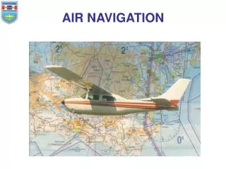
AIR NAVIGATION
Uncontrolled copy not subject to amendment. AIR NAVIGATION. Part 4. COMPASSES. Version 1.01. LEARNING OUTCOMES. On completion of this unit, you should: Be able to carry out calculations to determine aircraft distance, speed and time

AIR NAVIGATION
E N D
Presentation Transcript
Uncontrolled copy not subject to amendment AIR NAVIGATION Part 4 COMPASSES Version 1.01
LEARNING OUTCOMES On completion of this unit, you should: • Be able to carry out calculations to determine aircraft distance, speed and time • Understand the principles of vectors and the triangle of velocities to establish an aircraft’s track and ground speed
LEARNING OUTCOMES • Understand the principles of the 1 in 60 rule • Understand the types of compass systems used for air navigation, how they work and their limitations • Know the hazards that weather presents to aviation
You will have learnt about the difference between and YOU WILL HAVE GOT LOST using the Silva, a simple hand held compass TRUE NORTH MAGNETIC NORTH
To understand aircraft compasses, their strengths and weaknesses we need to look into the subject a little deeper
Shape of the magnetic field around a magnet The first thing you need to understand is the shape of the magnetic field around a magnet
The Earth’s magnetic field, follows the same pattern as the field round a bar magnet but needs a little explaining
The red end of a magnet (known as the North Pole) is in fact a north-seeking pole Therefore, as opposites attract it can be seen that if the red end of our compass needle is to point to the North Magnetic Pole then in reality the North Magnetic Pole must, in magnetic terms be a south pole
At our latitude, the lines of force point down at an angle (known as the angle of dip) of 65º; once the angle exceeds 75º (which occurs about 1200 miles from the Poles) the directional force becomes so weak as to render magnetic compasses virtually useless. Looking at the diagram on the left the lines of force are only parallel to the surface of the Earth at the Equator. Indeed, at the poles the lines of force are vertical! A compass needle will try to follow the lines of force but is constrained by the construction to stay almost horizontal The end result of this is that the more vertical the Earth’s field, the weaker the directional force on the horizontal compass needle becomes.
Aircraft Compasses We will now look at Aircraft Compasses There are 2 main types
N 33 30 In an aircraft, the simplest form of compass is the Direct Indicating Compass (shown right), which looks very similar to the car compass, which can be bought from accessory shops.
N 33 30
The Direct Indicating Compass The points of the compass are printed around the equator of the ball, & the heading is shown against an index mark on the bowl. The magnet is hidden in the ball. The Direct Indicating Compass (DIC), like the hand held Silva compass, has a magnet suspended in liquid, which helps to dampen any movement It has the appearance of a squash ball inside a goldfish bowl. on gliders the compass is on the cockpit coming
The Direct Indicating Compass The DIC has several serious limitations, so it is normally used as a standby Those limitations are:
The Suspended Magnet Will Only Give A Correct Reading In Steady Straight & Level Flight. During Turns & Acceleration The Magnet Is Swung To One Side And Gives False Readings
The DIC is located in the cockpit, and there it is affected by the magnetic fields emanating from both the metal the aircraft is made from and from the various electrical circuits in the aircraft. These other magnetic fields badly affect the accuracy of the DIC.
The driving power of the horizontal portion of the Earth’s magnetic field is only strong enough to turn a compass needle; it does not have sufficient torque to drive repeaters at other crew positions in the aircraft
The DIC only indicates magnetic heading, modern aircraft may require True or Grid headings
At high magnetic latitudes (above 70º North or South) the DIC becomes sluggish and unreliable because the angle of dip is so steep and the directional force is so weak.
Advantages of the DIC It is very simple and therefore reliable It is very cheap and lightweight It does not require any form of power and so will continue to work even after a total power failure in the aircraft.
To overcome the limitations of the DIC, the Gyro Magnetic Compass was invented
Gyro Magnetic Compass It’s made up of the following components:
A Magnetic Detector Unit, which electrically senses the direction of Earth’s magnetic field and is normally situated in the wing tip
Z AXIS FRAME ROTOR A gyroscope Y AXIS A Gyroscope, which continues to point to a fixed point in space, regardless of any manoeuvres the aircraft may make
An Error Detector that senses any difference between the gyro and magnetic headings and applies a correction to the gyro at a pre-set rate
A controller or computer that applies corrections to the gyro to correct for the rotation of the Earth and the aircrafts flight path around the Earth
Adisplay or displays to show the aircraft heading at required positions in the aircraft. Various amplifiers and motors to control the system and in some GMCs a roll cut out switch to minimise the effect of a turn on the Magnetic Detector Unit
The basic principle of the GMC is that it uses the long-term accuracy of the detector unit combined with the short-term accuracy of the gyro.
What this means is that the gyro, which is connected to the compass, is constantly corrected by the magnetic detector, which is correct during straight and level flight and is more accurate than the DIC because being situated in the wing it is less affected by the deviating forces from other extraneous magnetic fields in the aircraft
If a roll cut out switch is used no error is fed from the magnetic detector to the gyro in the turn, if a roll cut out is not present, the error correction rate is low enough to only make a small effect which is removed when the wings are levelled During a turn, the gyro (which is unaffected by turns) is more accurate
A gyro magnetic system has considerably more torque than a DIC and can therefore provide outputs to repeater units in other positions in an aircraft and/or computers in the aircraft. The output to these repeaters can be easily modified so that they can display either true or magnetic heading
Gyro Errors To overcome this the gmc has developed as a system where the gyro heading can be relied on for short period ( about 10 minutes ) As the gyroscope is a manufactured item, it cannot be perfect Over a period of time it will become inaccurate ( this is called gyro wander ). It can then be reset by reference to the magnetic detector
Inertial Navigation, GPS and Beyond Throughout the UK the variation errors on maps & charts are reasonably accurate, but if we go into polar regions we face 2 problems
TRUE NORTH MAGNETIC NORTH Problem 1 Variation values are unreliable and as large as 180 degrees between true & magnets poles
Problem 2 The second problem is that as the compass nears the magnetic pole the compass detector will try to point at it. this is called dip.
Inertial Navigation A modern aircraft with a heading error of one degree can easily have position errors in the order of 6 miles/hour, which nowadays is not acceptable. The Inertial Navigation System (INS) eliminates this problem and can align itself with True North without the need for variation
A typical inertial navigation system can achieve positional accuracies of one mile/hour. Whilst this accuracy may appear good, it is still a long way short of the latest development in navigation technology.
Using Ring Laser Gyros or Fibre Optical Gyros to feed an Inertial Reference System, which is paired with a Global Positioning System (GPS), can produce a position, which is accurate to within 5 metres The ultimate aim is to achieve millimetre accuracy, we are not there yet, but it will happen.