GPS Signal Structure
GPS Signal Structure. Sources: GPS Satellite Surveying, Leick Kristine Larson Lecture Notes http://www.colorado.edu/engineering/ASEN/asen4519/asen4519.html. GPS Signal Requirements. Method (code) to identify each satellite

GPS Signal Structure
E N D
Presentation Transcript
GPS Signal Structure • Sources: • GPS Satellite Surveying, Leick • Kristine Larson Lecture Notes http://www.colorado.edu/engineering/ASEN/asen4519/asen4519.html
GPS Signal Requirements • Method (code) to identify each satellite • The location of the satellite or some information on how to determine it • Information regarding the amount of time elapsed since the signal left the satellite • Details on the satellite clock status
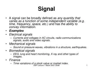
Important Issues to Consider • Methods to encode information • Signal power • Frequency allocation • Security • Number and type of codes necessary to satisfy system requirements
Overview of Satellite Transmissions • All transmissions derive from a fundamental frequency of 10.23 Mhz • L1 = 154 • 10.23 = 1575.42 Mhz • L2 = 120 • 10.23 = 1227.60 Mhz • All codes initialized once per GPS week at midnight from Saturday to Sunday • Chipping rate for C/A is 1.023 Mhz • Chipping rate for P(Y) is 10.23 Mhz
Digital Modulation Methods • Amplitude Modulation (AM) also known as amplitude-shift keying. This method requires changing the amplitude of the carrier phase between 0 and 1 to encode the digital signal. • Frequency Modulation (FM) also known as frequency-shift keying. Must alter the frequency of the carrier to correspond to 0 or 1. • Phase Modulation (PM) also known as phase-shift keying. At each phase shift, the bit is flipped from 0 to 1 or vice versa. This is the method used in GPS.
Modulo-2 recovery of GPS code Modulo-2 arithmetic: 0 + 0 = 0; 0 + 1 = 1; 1 + 0 = 1; 1 + 1 = 0 Bit shifts aligned MUST MOD-2 ADD RECEIVER-GENERATED CODE TO RECOVER
Superposition of codes - details • Superposition of two codes is not unique because the bit transition occurs at the same epoch; remember that both codes and phases are multiples of the fundamental frequency • Need to impose an additional constraint to arrive at a solution - quadri-phase-shift keying (QPSK), which puts the two codes 90° (p/2)
Phase and Quandrature - General General Expression: 2 All spectral components of y1(t) are 90° out of phase with those of y2(t). This allows this the two signals to be separated in the receiver.
GPS signal strength - frequency domain Note that C/A code is below noise level; signal is multiplied in the Receiver by the internally calculated code to allow tracking. C/A-code chip is 1.023 Mhz P-code chip is 10.23 Mhz Power = P(t) = y2(t) The calculated power spectrum derives from the Fourier transform of a square wave of width 2π and unit amplitude. Common function in DSP called the “sinc” function.
Digital Signal Processing Techniques • Filtering: Allows one to remove some portion of the frequency spectrum that may contain unwanted signal. • Low Pass Filter: lets all frequencies below a cutoff frequency through. • High Pass Filter: lets all frequencies above a cutoff frequency through. • Band Pass Filter: lets all frequencies within a specified window pass through. The window is called the passband
DSP Techniques, con’t. • Frequency Translation and Multiplication: technique to shift frequency spectrum of some signal to another portion of the frequency domain. • Up-conversion: translate signal to higher frequencies. • Down-conversion: translate signal to lower frequencies. Commonly done in GPS receivers. Multiply signal by sine function in a “mixer.” Special case is signal squaring and may be used to recover the pure carrier phase from a bi-phase modulated ranging signal.
DSP Techniques, con’t. • Spread Spectrum: broadly defined as a mechanism by which the bandwidth of the transmitted code is much greater than the baseband information signal (e.g. the navigation message in GPS) • FDMA: Frequency Division Multiple Access. Requires different carriers. Used by GLONASS. • TDMA: Time Division Multiple Access. Several channels share transmission link. Used by many cellular telephone providers and LORAN-C. • CDMA: Code Division Multiple Access. Requires pseudorandom codes by transmitted and also generated for correlation within the receiver. Used by GPS.
DSP Techniques, con’t. • Cross-correlation: Used by GPS receivers to determine what signal is coming from a specific satellite. Can be generalized to extracting information from any multiplexed digital signal.
PRN Cross-correlation Correlation of receiver generated PRN code (A) with incoming data stream consisting of multiple (e.g. four, A, B, C, and D) codes
Schematic of C/A-code acquisition Since C/A-code is 1023 chips long and repeats every 1/1000 s, it is inherently ambiguous by 1 msec or ~300 km. Must modulo-2 add the transmitted and received codes after correlation to increase SNR and narrow bandwidth.
Methods to Cope with Anti-spoofing • Anti-spoofing: Implemented in 1994 to make P-code unavailable to non-military users. Encrypted P-code is referred to as Y-code. • Squaring: Yields half-wavelength carrier and greatly reduces SNR. Old technology. • Code-aided squaring: Uses mathematical similarity of the Y-code to P-code. L1 carrier is down-converted and multiplied with a local replica of the P-code, then squared. Results in less reduction of SNR than simple squaring.
Anti-spoofing Methods, con’t. • Cross-correlation: Takes advantage of the fact that both L1 and L2 are modulated with the same P(Y)-code, despite lack of knowledge of the actual P-code. Yields the difference in pseudoranges, P1(Y) - P2(Y), and the phase difference of L1 and L2. Again less SNR loss compared with squaring. Can be difficult to track at low elevation angles. Technique employed in Trimble 4000SSi/SSE. • Z-tracking: Takes advantage of the fact that Y-code is the modulo-2 sum of the P-code with a lower encryption rate. Yields L1 and L2 Y-code pseudoranges and the full carrier phases of L1 & L2. This method yields the best SNR. Multipath performance is better than other methods. Technique employed in Ashtech Z-12 and micro-Z.
AS Technologies Summary Table Ashtech Z-12 & µZ Trimble 4000SSi From Ashjaee & Lorenz, 1992