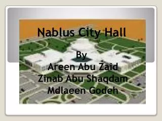
Nablus City Hall
Nablus City Hall. By Areen Abu Zaid Zinab Abu Shaqdam Mdlaeen Godeh. Chapters. Chapter one:Introdution. Chapter two: architectural design. Chapter three: Inviromental design. Chapter four: Structural design. Chapter five: Internal system design. Chapter One : Introduction.

Nablus City Hall
E N D
Presentation Transcript
Nablus City Hall By Areen Abu Zaid Zinab Abu Shaqdam Mdlaeen Godeh
Chapters Chapter one:Introdution Chapter two: architectural design Chapter three: Inviromental design Chapter four: Structural design Chapter five: Internal system design
Chapter One : Introduction A building lies in the western side of Nablus , this building consist of two stories of (8000 m2) , and height of each storey is (5m). Ground floor consists of two main halls, library, cafeteria, bathrooms, and security and Theatre. 1st floor consists of computer hall, bathrooms, cafeteria , theare first floor.
Buildings of the project: 1-Building Main Halls 2-theater of the project 3-Central cafeteria 4-A major public library 5-Computer hall
Nablus City Hall Architicture Design
Chapter Two Nablus City Hall Structural Design
Design Data • Yielding strength of steel, fy = 4200 kg/cm2. • Modulus of elasticity of steel, Es = 2.04x10⁶ kg/cm2. • Modulus of elasticity of concrete, Ec = 15100 √ fc . • B300 → fc = 240 kg /cm2 → Ec = 2.34×10⁵ Kg /cm2
Design Data • Unit weights of materials: Reinforced concrete = 2.5 ton/m3 . Blocks = 1.2 ton/m3 . Stone =2.6 ton/m3. Sand =2 ton/m3. • soil bearing capacity = 1.5kg/cm2 .
Design Data Design loads: live load is 500 kg/m2 =0.5 T/m2 for grond and first floor __ L.L For final roof=0.2 T/m2 . Super imposed dead load is 0.3 T/m2 . Slap thickness = 20 cm solid slap (roof) Stair thickness =25 cm Wall thickness = 20 cm
Structural analysis laws and checking the results: Theatre Block Service Block
In this block we use pannel beam system using solid slab 20 cm depth with continuos beams carried on shear wall.because of long spans and to achieve theatre function. first floor Ground floor
Design steel for ground floor as the shear wall carry the load Moment from sap (M=20t.m/m)
Design steel for first floor as the shear wall carry the load Moment from sap (M=20t.m/m)
Case 2: As another solution if there is compressive refile siolwith minnimum load 98% underground use 7 Ø12/ m in two direction upper and bottom steel use minnimum steel.
Design of beam After design on sap and select beam dimension(120*80cm) approximetly each 4 m, the figure from sap show steel value as follow: Use 22 Ø20 mm for the bottom For the top steel use As minUse 12 Ø18 Use Ø10/20cm Stirups
Design for exterior wall: From sap we find F11 = 14 t/m Use 5 Ø12/ m Horizontal Steel
We find from sap F22 = 46t/m Shear wall reinforcement Use 7 Ø16/ m Vertical Steel
Footing design: After analysis on sap and finding load on footing per meter : DL on Foundation = 40t/m LL on Foundation = 20t/m Section in footing
Column design • The design load can be calculated using the following equation: • Pd= 𝜙Pn=𝜙*λ {0.85* fc(Ag-As) + As*f y}. • 𝜙 = 0.65 for tied columns. • 𝜙 = 0.7 for spiral columns. • λ = 0.8 for tied columns. • λ = 0.85 for spiral columns.
Chapter three Nablus City Hall Electrical Design
Lighting calculation N=E*A/(n* FL*Ku*Km) Where: N=number of units in place(#of luminair). E=Illuminance,measured by lux. A=area of space. n= number of lamp. FL=Flux (lumen/lamp). Ku=utilization factor (depend on room factor ). Km=maintenance factor.
Calculation of the (MDB) and cross section area of cables Total current for lighting = 80 A We select diameter of cables D cables = 25 mm
Total Current for sockets = 40 Amp and use cable with diammeter = 16 mm