
Chapter 10
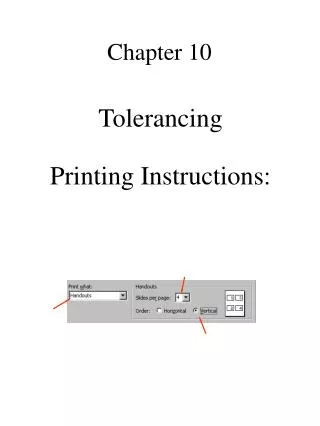
Print handouts Select File, Print Edit the following selections to read: Select the OK button. Chapter 10. Tolerancing Printing Instructions:. Tolerancing. Tolerances are used to control the variation in size that exists on all manufactured parts.

Chapter 10
E N D
Presentation Transcript
Print handouts Select File, Print Edit the following selections to read: Select the OK button Chapter 10 Tolerancing Printing Instructions:
Tolerancing • Tolerances are used to control the variation in size that exists on all manufactured parts. • The amount that a size is allowed to vary depends on the function of the part & its assembly. • electric drill vs. jet engine • The more accuracy required in a part (smaller tolerance) the greater the cost. • Tolerances allow for interchangeable parts, which permits the replacement of individual parts in an assy. instead of replacing the whole system if a part goes bad or fails.
Tolerance • Tolerance is the total amount a dimension may vary. It is the difference between the maximum size and the minimum size. • Tolerances can be expressed on a drawing in several ways: • direct limits, or as tolerance values applied directly to a dimension. (Fig. 10.8) • geometric tolerances (Fig. 10.25) • notes referring to specific conditions • A general tolerance note in the titleblock. (Fig. 10.7)
Dimensions • Limit dimensions: • Plus/minus dimensions: • unilateral • bilateral
Tolerancing Terms • Nominal size: the “name” or general size. Often expressed as a fraction. • Basic size: the theoretical size used as a starting point for the application of tolerances. Nominal size in decimal format. • Actual size: the measured size of the finished part. • Limits: the maximum & minimum sizes shown by the toleranced dimension. • Allowance: the min. clearance or max. interference between 2 parts. • MMC: the condition of a part in which it contains the most amount of material. EX: biggest shaft or smallest hole. • LMC: the condition of a part in which it contains the least amount of material.
Tolerance, MMC, LMC? • Limit dimensions: • Plus/minus dimensions: • unilateral • bilateral
Complete Worksheet TOL-1 • Remember x.xxxx • I.e. 0.1234 • I.e. 2.1200
Fit • Fit: the degree of tightness between mating parts. • The three most common types of fit found in industry are: • Clearance fit - there is always a space between the 2 mating parts. (shaft is smaller than the hole) • Interference fit - the 2 mating parts always interfere with one another in assembly. (shaft is bigger than the hole) • Transition fit - sometimes a clearance fit & sometimes an interference fit between the mating parts.
Do on ownpage 335, Figure 10.1a • Hole Tolerance? • Shaft Tolerance? • Minimum clearance? • Maximum clearance? • Allowance?
ANSI Standard Fits • A group of English usit tolerance relationships called preferred precision fits have been developed. They are specified in ANSI B4.1. • The five classes are: • Running & sliding fits (RC) • Clearance locational fits (LC) • Transition locational fits (LT) • Interference locational fits (LN) • Force or shrink fits (FN) • These tolerances are specified in Appendix 5 through 9, pages a25-a32. The values in these tables are given in THOUSANDTHS of an inch. Example: 1.2 = 0.0012
Class RC9: Running & Clearance FitBasic DIA = 2.0000 • Hole • Shaft • Shaft Tolerance = • Hole Tolerance = • Max. Clearance = • Min. Clearance =
Class FN2:Medium Drive fitBasic DIA = 0.5000 • Hole • Shaft • Shaft Tolerance = • Hole Tolerance = • Max Interference = • Min Interference =
Metric Fit - Terms • Basic size: size to which limits of deviation are assigned. (Fig.10.1, p 343) • Must be same for both parts • Basic sizes selected from chart in Table 10.2 • Deviation: difference between the actual size and the basic size. (Fig. 10.14) • Upper deviation: difference between the max. size limit & the basic size. • Lower deviation: difference between the min. size limit & the basic size. • Fundamental deviation: the deviation closest to the basic size. (Fig. 10.18) • Capital H indicates Hole • Lowercase letter, I.e. f , indicates shaft
Metric Fit – Terms cont’d • International Tolerance Grade (IT): a group of tolerances that vary depending upon the basic size, but have the same level of accuracy within a given grade. (Fig 10.18) • There are 18 IT grades. The smaller the grade number, the smaller the tol. zone. • See Appendix 10 for IT grades.
Preferred Metric Fits • There are 2 systems used to indicate preferred fits in the metric system. • Hole basis: the system of fits where the min. hole size is the basic size. The fundamental deviation for a hole basis system is indicated by a capital “H”. • EX. 50H8 (50 = DIA in mm) (Basic size) (H = using Basic Hole system) (fundamental deviation) (8 = closest running fit) (IT grade) • For mating part 50H8/f7 (Appendix 11) • Hole Limits? • Shaft Limits? • Fit?
Preferred Metric Fits • The second system used to indicate preferred fits in the metric system. • Shaft basis: the system of fits where the max. shaft size is the basic size. The fundamental deviation for a shaft basis system is indicated by a lowercase letter. • EX. 50h7 (50 = DIA in mm) (Basic size) (h = using Basic Shaft system) (fundamental deviation) (7 = closest running fit) (IT grade) • For mating part 50F8/h7 (Appendix ?) • Limits and Fits? • Hole Limits? • Shaft Limits? • Fit?
Try the following problem • Basic DIA 41mm • Use Hole Basis System • Sliding
Try the following problem • Basic DIA 41mm • Use Shaft Basis System • Sliding
Try the following problem • Basic DIA 58mm • Use Shaft Basis System • Force Fit
Look Up • What type of fit is a 6 H7/s6? • Hole or Shaft Basis System?


