Download
1 / 1
10 likes | 149 Vues
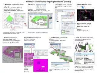
This guide provides a comprehensive method for accurately mapping images onto site geometry using MicroStation and Photoshop. Starting with a drawing as a base, you will learn to attach materials to dummy geometry, create materials in the Material Editor, and print maps for precise registration. The process includes creating projections based on dummy geometry and ensures that all elements are correctly associated and locked to their origins for consistent results. Follow the outlined steps to streamline your workflow and maintain quality in your projects.

E N D
Workflow: Accurately mapping images onto site geometry 1.Microstation. Use drawing as base for image map. 4. AttachMaterial to dummy geometry. 2. Photoshop 3.Microstation. Create material in Material Editor. Use jpg as Pattern Map.` Print to pdf & import into Photoshop (use sheet definition to maintain proportion & registration of image for future changes) Rasterize: Resolution controls final size / quality – keep consistent for future changes Save copy as JPG Need actual size for material definition = printed size. Use Master units. Repeat On. Mapping: Directional Drape - Top Actual size Example sheet definition: A3 sheet @ 1:250 (smaller sheet size = thicker lines) (use png raster format for transparency) 5. Move dummy geometry in Illustration Display mode. Preview allows you to position map accurately by eye against model. 6. Create Projection Group based on dummy geometry . Create logical name 7. Attach Projection to actual mesh/ geometry Attach material first, then attach projection. 8. Finish. Check Element Information to see projection group has been correctly assigned Map will now be locked to origin and will not move with the geometry. The same projection group can be used for multiple elements. Click sequence: 1-Select dummy geometry 2 – Accept while snapped to centre Select new projection group from drop down.