UML FUNDAMENTALS
1.85k likes | 2.06k Vues
The Unified Modeling Language (UML) is a standard way to visualize and document the design and analysis of systems. It combines various object-oriented methods, such as Booch, OMT, and OOSE, to provide a comprehensive modeling language. UML facilitates better understanding and communication among stakeholders by offering a variety of diagram types, such as Use-Case, Class, and Sequence diagrams, each serving distinct purposes. It aids in system discovery, helps lower development and maintenance costs, and standardizes system documentation, enhancing clarity and reuse.

UML FUNDAMENTALS
E N D
Presentation Transcript
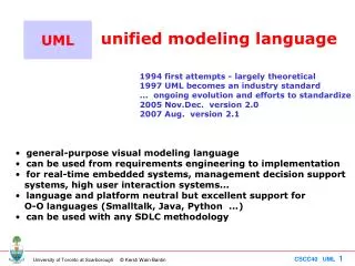
UML Unified Modelling Language Visualising and documenting analysis and design effort. • Unified because it … • Combines main preceding OO methods (Booch by Grady Booch, OMT by Jim Rumbaugh and OOSE by Ivar Jacobson) • Modelling because it is … • Primarily used for visually modelling systems. Many system views are supported by appropriate models • Language because … • It offers a syntax through which to express modelled knowledge
UML Partners The list is quite an impressive one: • Hewlett-Packard • IBM • Microsoft • Oracle • i-Logix • Intelli Corp. • MCI Systemhouse • ObjectTime • Unisys • Sterling Software • Rational Software • ICON computing • Platinum Technology • and others…
andso…What is UML? • A language for capturing and expressing knowledge • A tool for system discovery and development • A tool for visual development modelling • A set of well-founded guidelines • A milestone generator • A popular (therefore supported) tool
and…What UML is not! • A visual programming language or environment • A database specification tool • A development process (i.e. an SDLC) • A panacea • A quality guarantee
What UML can do for you Help you to: • Better think out and document your system before implementing it • “forecast” your system • Determine islands of reusability • Lower development costs • Plan and analyse your logic (system behaviour) • Make the right decisions at an early stage (before committed to code) • Better deploy the system for efficient memory and processor usage • Easier maintenance/modification on well documented systems • Lower maintenance costs • Establish a communication standard • Minimise “lead-in” costs
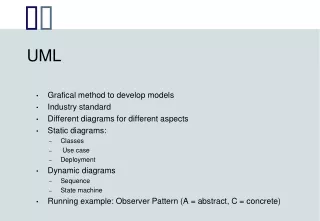
UML Views Functional Non-functional Organisational Diagrams 9 diagrams (see further on) Model Elements Symbology / notation General Mechanisms Adornments Notes Specifications UML components
The Case “for” Diagrams • Aesthetic • Descriptive • Compressive • Simple • Understandable • Universal • Formalise-able / Standardise-able
The Case “against” Diagrams • Not inherent knowledge • Easily cluttered • Require some training • Not necessarily revealing • Must be liked to be accepted and used • Effort to draw
UML diagrams Use-Case Static Structure Object Class Interaction Sequence Collaboration State Activity Implementation Component Deployment UML diagrams
UML Diagrams • Use-Case(relation of actors to system functions) • Class(static class structure) • Object(same as class - only using class instances – i.e. objects) • State(states of objects in a particular class) • Sequence(Object message passing structure) • Collaboration(same as sequence but also shows context - i.e. objects and their relationships) • Activity(sequential flow of activities i.e. action states) • Component(code structure) • Deployment(mapping of software to hardware)
UML Diagram Philosophy Any UML diagram: • Depicts concepts • as symbols • Depicts relationships between concepts • as directed or undirected arcs (lines) • Depicts names • as labels within or next to symbols and lines
The Main 4 UML Diagrams • Use-Case • Class • Sequence • State
The Other 5 UML Diagrams • Object • Collaboration • Activity • Component • Deployment
UML DM Requirements Gathering Analysis Design Development Deployment UML Development Model
Use-Case Diagrams (UCDs) • A use-case is… • a simplification of (a part of)a business process model • a set of activities within a system • presented from the point of view of the associated actors (i.e. those actors interacting with the system) • leading to an externally visible result • Whatis the model supposed to do? • offer a simplified and limited notation • allow other diagrams used to support (realise) it • combinatorial with prototypes as complementary information • not intended to model functional decomposition
Use-Case Diagrams (UCDs) Components: use-cases and actors • a use-case must always deliver a value to an actor • the aggregate of all use-cases is the system's complete functionality Goals: • consolidate system functional requirements • provide a development synchronisation point • provide a basis for system testing • provide a basic function-class/operation map
UCD Components • The use case itself is drawn as an oval. • The actors are drawn as little stick figures. • The actors are connected to the use case with lines. System Use-case symbol Actor symbol System boundary Actor1 «extend» «include» Relationships and connectors
UML Actors • An actor • Is a class that forms a system boundary • participates in a use-case • is not within our responsibility as systems analyst/s and/or designer/s • Examples are • end-users (roles) • external systems (co-operations) • time related events (events) • external, passive objects (entities)
UML Actor Classification • A primary actor uses the system's primary functions (e.g. a bank cashier); • A secondary actor uses the system's secondary functions (e.g. a bank manager, system administrator); • An active actor initiates a use-case; • A passive actor only participates in one or more use-cases.
Identifying UML Actors Ask yourself the following questions: • Who are the system’s primary users? • Who requires system support for daily tasks? • Who are the system’s secondary users? • What hardware does the system handle? • Which other (if any) systems interact with the system in question? • Do any entities interacting with the system perform multiple roles as actors? • Which other entities (human or otherwise) might have an interest in the system's output?
«actor» The guy UML Actor Notation and Generalisation Examples Staff The guy Clerical staff Academic staff Support staff
UML Use-Cases (UCs not UC Diagrams UCDs) Definition:"A set of sequences of actions a system performs that yield an observable result of value to a particular actor.“ Use-case characteristics: • Always initiated by an actor (voluntarily or • involuntarily); • Must provide discernible value to an actor; • Must form a complete conceptual function. (conceptual completion is when the end observable value is produced)
UC Description Criteria Use-Case Number (ID) and Name • actors • pre- and post-conditions • invariants • non-functional requirements • Behaviour modelled as: • activity diagram/s • decomposition in smaller UC diagrams • error-handling and exceptions • Rules modelled as: • activity diagram/s • services • examples, prototypes, etc. • open questions and contacts • other diagrams Use-case Described by
UC Description Example UC: Login authentication • User • Disable access - Enable access • Logged in user = valid user • Login delay; line security • Behaviour modelled as: • activity diagram/s • decomposition in smaller UC diagrams • Invalid login name; interrupt entry • Rules modelled as: • activity diagram/s • Log, pass prompts; authenticate • examples, prototypes, etc. • open questions and contacts • other diagrams (realisations)
Consolidating UC Descriptions Ask yourself these questions: • Do all actors interacting with a given UC have communication association to it? • Are there common roles amongst actors? • Are there UC similarities? • Are there special cases of a UC? • Are all system functions catered for by UCs?
UCD Relationships (1/2) • Association relationship • Extend relationship • Include relationship • Generalisation relationship «extend» «include»
UCD Relationships (2/2) • Associations • Links actors to their UCs • Use (or include) • Drawn from base UC to used UC, it shows inclusion of functionality of one UC in another (used in base) • Extend • Drawn from extension to base UC, it extends the meaning of UC to include optional behaviour • Generalisation • Drawn from specialised UC to base UC, it shows the link of a specialised UC to a more generalised one
UCD Definition Summary Use-Case diagrams: • show use-cases and actors • connected by “associations” • refined by inheritance stereotypes • “uses” • re-use of a set of activities (use-cases) • partitioning of activities • points to the re-used use-case • “extends” • variation of a use-case • points to the standard use-case
UCD Relationship Example (2/2) «extend» elicit customer needs make an interview «include» produce a SRS
What a UCD is - and what it isn’t • Attention focuser on the part of the business process that is going to be supported by the IS. • It is the end-user perspective model. • It is goal driven • Helps to identify system services. • Are not used as DFDs. • Sequences, branching, loops, rules, etc. cannot (and should not) be directly expressed. • Are often combined with activity diagrams, which serve as their refinement.
UCD Case Study (1/3) Vending Machine • After client interview the following system scenarios were identified: • A customer buys a product • The supplier restocks the machine • The supplier collects money from the machine • On the basis of these scenarios, the following three actors can be identified: • Customer; Supplier; Collector
UCD Case Study (3/3) • Introducing annotations (notes) and constraints.
Testing UCs • Verification • Confirmation of correct development according to system requirements. • Validation (only when working parts become available) • Confirmation of correct system functionality according to end-user needs. • Walking the UC • This is basically, interchangeable role play by the system developers.
Workshop Activity -1- Create a simple UCD (i.e. no “uses” or “extends” relationships) for a course registration system described as follows: “The course registration system should allow students to register for and drop courses. The system’s administrator should be able to add and delete courses from the system as well as to cancel planned courses. If a planned course is cancelled the relevant instructor should be notified through the system.” (Loosely adapted from Lee, 2002)