Potential Flow Theory : Incompressible Flow
Potential Flow Theory : Incompressible Flow. P M V Subbarao Professor Mechanical Engineering Department IIT Delhi. A mathematical Tool to invent flow Machines.. . Basic Elements for Construction Flow Devices . Any fluid device can be constructed using following Basic elements.

Potential Flow Theory : Incompressible Flow
E N D
Presentation Transcript
Potential Flow Theory : Incompressible Flow P M V Subbarao Professor Mechanical Engineering Department IIT Delhi A mathematical Tool to invent flow Machines.. ..
Basic Elements for Construction Flow Devices • Any fluid device can be constructed using following Basic elements. • The uniform flow: A source of initial momentum. • Complex function for Uniform Flow : W = Uz • The source and the sink : A source of fluid mass. • Complex function for source : W = (m/2p)ln(z) • The vortex : A source of energy and momentum. • Complex function for Uniform Flow : W = (ig/2p)ln(z)
THE DIPOLE • Also called as hydrodynamic dipole. • It is created using the superposition of a source and a sink of equal intensity placed symmetrically with respect to the origin. • Complex potential of a source positioned at (-a,0): • Complex potential of a sink positioned at (a,0): • The complex potential of a dipole, if the source and the sink are positioned in (-a,0) and (a,0) respectively is :
Streamlines are circles, the center of which lie on the y-axis and they converge obviously at the source and at the sink. Equipotential lines are circles, the center of which lie on the x-axis.
THE DOUBLET • A particular case of dipole is the so-called doublet, in which the quantity a tends to zero so that the source and sink both move towards the origin. • The complex potential of a doublet is obtained making the limit of the dipole potential for vanishing a with the constraint that the intensity of the source and the sink must correspondingly tend to infinity as a approaches zero, the quantity
Uniform Flow Past A Doublet • The superposition of a doublet and a uniform flow gives the complex potential
Find out a stream line corresponding to a value of steam function is zero
There exist a circular stream line of radium R, on which value of stream function is zero. • Any stream function of zero value is an impermeable solid wall. • Plot shapes of iso-streamlines.
Note that one of the streamlines is closed and surrounds the origin at a constant distance equal to
Recalling the fact that, by definition, a streamline cannot be crossed by the fluid, this complex potential represents the irrotational flow around a cylinder of radius R approached by a uniform flow with velocity U. Moving away from the body, the effect of the doublet decreases so that far from the cylinder we find, as expected, the undisturbed uniform flow. In the two intersections of the x-axis with the cylinder, the velocity will be found to be zero. These two points are thus called stagnation points.
with Equation of zero stream line:
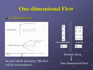
V2Distribution of flow over a circular cylinder The velocity of the fluid is zero at = 0oand = 180o. Maximum velocity occur on the sides of the cylinder at = 90oand = -90o.
Pressure distribution on the surface of the cylinder can be found by using Benoulli’s equation. Thus, if the flow is steady, and the pressure at a great distance is p,
Anatomy of an airfoil • The straight line that joins the leading and trailing ends of the mean camber line is called the chord line. • An airfoil is defined by first drawing a “mean” camber line. • The length of the chord line is called chord, and given the symbol ‘c’. • To the mean camber line, a thickness distribution is added in a direction normal to the camber line to produce the final airfoil shape. • Equal amounts of thickness are added above the camber line, and below the camber line. • An airfoil with no camber (i.e. a flat straight line for camber) is a symmetric airfoil. • The angle that a freestream makes with the chord line is called the angle of attack.
Conformal Transformations P M V Subbarao Professor Mechanical Engineering Department IIT Delhi A Creative Scientific Thinking .. ..
INTRODUCTION • A large amount of airfoil theory has been developed by distorting flow around a cylinder to flow around an airfoil. • The essential feature of the distortion is that the potential flow being distorted ends up also as potential flow. • The most common Conformal transformation is the Jowkowski transformation which is given by To see how this transformation changes flow pattern in the z (or x - y) plane, substitute z = x + iy into the expression above to get
This means that For a circle of radius r in Z plane x and y are related as:
Consider a cylinder in z plane In z – plane
Translation Transformations • If the circle is centered in (0, 0) and the circle maps into the segment between and lying on the x axis; • If the circle is centered in (xc ,0), the circle maps in an airfoil that is symmetric with respect to the x' axis; • If the circle is centered in (0,yc ), the circle maps into a curved segment; • If the circle is centered in and (xc , yc ), the circle maps in an asymmetric airfoil.