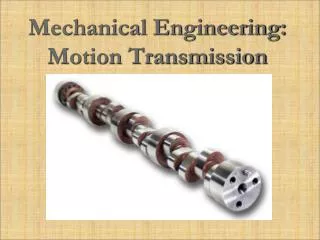
Mechanical Engineering: Motion Transmission
Mechanical Engineering: Motion Transmission. Screw Gear System. A screw gear, also known as a worm gear, is a spirally threaded shaft and a wheel a wheel with teeth that mesh into it. There are two types of screw gear systems that can transform motion from rotational -> translational.

Mechanical Engineering: Motion Transmission
E N D
Presentation Transcript
Screw Gear System • A screw gear, also known as a worm gear, is a spirally threaded shaft and a wheel a wheel with teeth that mesh into it. • There are two types of screw gear systems that can transform motion from rotational -> translational.
Screw Gear System • Type 1: The screw gear is the driver that transforms rotational motion into translational motion. The nut must be guided so that it does not rotate with the screw.
Screw Gear System • Type 2: The nut is the driver and transforms rotational motion into translational motion. The nut must be fixed in a way that only allows for rotation.
Cam and Follower • A cam is a mechanism used especially for transforming rotational motion to translational motion. • A cam and follower is formed by direct contact of two mechanisms: the driver (cam) and the driven part (follower). • The shape of the contacting surfaces determines the movement of the mechanism.
Connecting Rods • A connecting rod acts as a link for connecting motion from the crank to the slide. • Together they form a simple mechanism that converts translational motion to rotational motion. • Connecting rods allow for reversibility: able to convert rotational motion into translational motion.
Connecting Rods Connecting Rod
Slides • Slides can allow for the transformation of linear motion into rotational motion and vice versa.
Slides Slide
Cranks • Cranks are similar to a cam. They convert rotational motion into translational motion and vice versa. • The difference between cams and cranks is that cranks only work rotationally and only ever have one drive action per revolution.
Rotating Slider Crank Mechanism • Slider-crank mechanisms involve both rotational and translational motion. • The crank rotates at constant speed to repeatedly move an object. • A simple way to reversibly convert rotational motion to translational motion.
Rack-and-Pinion • Cranks are similar to a cam. They convert rotational motion into translational motion and vice versa. • The difference between cams and cranks is that cranks only work rotationally and only ever have one drive action per revolution.