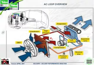
AC LOOP OVERVIEW
P F. Evaporator. High pressure. Condensor. P C. Expansion valve. Low pressure. GMV. Condenser. P W. Compressor. Receiver drier. Pressure switch. AC LOOP OVERVIEW. Condenser. Compressor. Control panel. Bottle. HVAC unit. AC LOOP OVERVIEW. (4) Condenser. T° ext.

AC LOOP OVERVIEW
E N D
Presentation Transcript
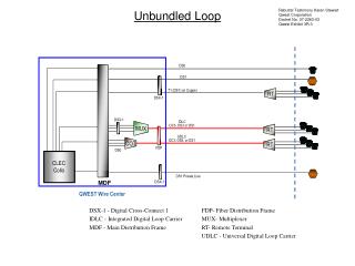
PF Evaporator High pressure Condensor PC Expansion valve Low pressure GMV Condenser PW Compressor Receiver drier Pressure switch AC LOOP OVERVIEW
Condenser Compressor Control panel Bottle HVAC unit AC LOOP OVERVIEW
(4) Condenser T° ext Fluid Pressure & Temperature PC High P, T° 70°C20 bars (1) Expansion valve (3) Compressor PW (2) Evaporator Low P, T° 0°C3 bars PE Stored energy in the fluid T° habitacle GAS STATE LIQUID STATE AC LOOP PRINCIPLE (2/3) Energy balance :PE + PW = PC
AC LOOP CYCLE ON DIAGRAM OF MOLLIER Pressure bar 65° 60° 0° 50.0 De-overheat Sub-cooling CONDENSATION 60° 40° 10.0 DETENT COMPRESSION 20 5.0 EVAPORATION 0° Liquid Superheat -20 Saturated liquid 1.0 Liquid + Vapour -40° 0.5 Saturated vapour Vapour -60° 0.2 0.4 0.6 0.8 0.1 0° 100° 100 400 200 300 500 Enthalpy kJ/kg
COMPRESSOR 20 bars 110°C Temperature sensor CONDENSER 3 bars 5°C EVAPORATOR G.M.V. PRESSURE SWITCH 3 bars 3°C 3 bars -1°C 19 bars 60°C 4 bars 16°C RECEIVER DRIER EXPANSION VALVE 19 bars 60°C AC LOOP WITH AN EXPANSION VALVE
COMPRESSOR 3 bars 20 bars CONDENSER 5°C 110°C ACCUMULATOR Temperature sensor EVAPORATOR PRESSURE SWITCH G.M.V 3 bars 3°C 3 bars -1°C 19 bars 5 bars 60°C 16°C ORIFICE TUBE 19 bars 60°C AC LOOP WITH AN ORIFICE
THE CONDENSER : TECHNOLOGIES Brazed tubes Serpentin technology Mechanical assembly Initial technology Medium performances High increasing Available technology Low performance : it disapears for vehicle with large High performances front surface Lowcost
THE EXPANSION VALVE (TXV) • EXPANSION VALVE (TXV) - MAIN FUNCTIONS • Sudden pressure drop: High to low pressure • Control the refrigerant cooling • Control of the superheat by controling the mass flow • EXPANSION VALVE (TXV) - CRITERIAS OF CHOICE • Performance max in the car • Freezing of the evaporator • Superheat level • Stability of the system It is between the drier receiver and the evaporator, linked to the evaporator
THE ORIFICE TUBE • ORIFICE TUBE - MAIN FUNCTIONS • IDEM TXV BUT NO CONTROL OF SUPERHEAT & MASS FLOW • Orifice Tube • Air outlet temperature (power) • Sub-cooling • Superheat outlet evaporator • Pressure and temperature outlet compressor It is always at the evaporator inlet
THE EVAPORATOR Between expension device and the compressor. In the vehicle, it is in the HVAC unit, under the cockpit.
THE EVAPORATOR : FUNCTIONS • To supply the required cooling power for the car cabin • The required thermal power is defined during the theorical sizing of the A/C loop components. It depends on the thermal balance of the car cabine and on customer’s specification • The evaporator is selected in the Valeo range to fit the thermal performance together with de contraintes : • economical constraints • car integration & environment constraints
THE DRIER RECEIVER • FUNCTION 1 : • To supply the expansion valve with liquid refrigerant • To constitute a liquid reserve • FUNCTION 2 : Dehumidification of the circulating fluid • FUNCTION 3 : To filter solid impurities • SOLUTIONS : • Glass fibre disks with a hole for the diver tube • Or thermoformed bags containing the desiccant and the filter, in an annulus It is between the condenser and the expansion valve (TXV) in the engine compartment
THE ACCUMULATOR • Accumulator functions: • To supply the compressor with entirely gaseous refrigerant • To dehumidify and filter the refrigerant / oil mixture • To ensure that the oil returns to the compressor • Principal characteristics of an accumulator : • system used to separate liquid / vapour • useful volume • desiccant mass • position of the oil return hole It is between the evaporator and the compressor in the engine compartment
TUBES & HOSES • Tubes & Hoses Functions • To transport R134a and limit leaks • To resist to ambience and To R143A • R134a pressure & temperature • Ambience temperature and humidity & fluid bonnet • To reduce noise and vibration transmission • Not to reduce the A/C Loop performances • to reduce pressure drop / insulate (LP line f.g.) • Easy to mount on the vehicle (sensors & charge connection) They link the different components to make the refrigerant circulating in the AC loop
五 点 最 合 理 的 反 映 • 1〕测量:至少每30000公里检测风量, 确认过滤网是否脏污过度 • 2〕查找:先查找泄漏点, 后补加R134a • 3〕确认:确认补加的润滑油,O型圈(EPDM〕,是指定的产品,确保相融性 • 4〕精确:制冷剂、润滑油的加注量,多少都不利 • 5〕更换:最好每次检修、每两年更换储液罐
汽车文化 • 宣传正确的使用习惯 × • 加强服务: