Computational Paradigms and Process Frameworks
280 likes | 378 Vues
Explore state-oriented models like finite state machines and state diagrams, as well as function-oriented models focusing on actions and processes. Learn to use data flow diagrams and process frameworks to design software systems effectively.

Computational Paradigms and Process Frameworks
E N D
Presentation Transcript
State-Oriented Models • Examples: • Automata (DFAs, NFAs, PDAs) • Turing Machines • A finite state machine is a hypothetical machine that can be in only one of a given number of states at a specific time. • In response to a stimulus, the machine performs an action (possibly generating output) and changes state. • State diagrams capture the behavior of the machine.
button pushed / turn power off On Off button pushed / turn power on Toggle Switch State Diagram
Open timer button / beep timer button / beep door opened door closed Set time Disabled door opened Idle start button / cooking light on door closed Cooking time out / cooking light off door opened / cooking light off Microwave Oven State Diagram
State Machines • Actions are processes that occur “quickly” and are not interruptible. • A single state in a state diagram may be decomposed into several states in a less abstract view.
F X Y Function-Oriented Models • The specification of the external behavior of a system is primarily a description of how the system outputs relate to the system inputs. The classic example for function-oriented techniques is the mathematical function.
F X Y Function-Oriented Models (2) • All actions are atomic, effectively instantaneous • There are no observable intermediate states • No action, once started, is affected by any external state Function F maps a value X to a value Y. F(X) = Y. P X Y Process P consumes input X and produces output Y
Function-Oriented Models (3) • Sequential processes may be modeled as composition of functions: P1 P2 P3 X Y F3(F2(F1(X))) = Y
DoubleSquare arrow Open-ended Rectangle Data Flow Diagrams Source or destination of data Flow of data Process which transforms a flow of data Rounded Rectangle Store of data
AccountManager Employee EmployeeTimecards EmployeeRecords Payroll System DFD EmployeeData Paycheck Number ofDependents PaycheckInfo CalculateWithholding AccountingData Report FormatPaycheck GrossPay GenerateReport CalculateGross Pay Time In/Time Out HoursWorked
What Are We Modeling? • State machine and data flow diagrams can be used to help specify the design of a software system. In this case they are showing state transitions or data flows within the system to be built. • The same notations could be used during analysis to document state transitions or data flows in the real world (the problem domain). • For example, employee timecards might be a database with timecard data, or it might be a stack of physical cards. Calculate Gross Pay might be a function of the system, or it might be a process performed by hand.
Employee AccountManager What Are We Modeling? (2) • These same notations could even be used to specify requirements of the system: EmployeeData Report ComputePayroll Paycheck • Here we are showing only data flows into and out of the system. We are not specifying what happens within the system.
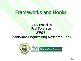
Process Frameworks • Define the basic elements of a process model and how they relate to each other. • Define how process models are decomposed into greater detail.
IDEF0/SADT Process Model • Input • Arrow entering the left side of the box are inputs. Inputs are transformed or consumed by the function to produce outputs. • Control/Constraint • Arrows entering the box on the top are controls. Controls specify the conditions required for the function to produce correct outputs. • Output • Arrows leaving the box on the right are outputs. Outputs are the data or objects produced by the function. • Resource/Mechanism • Identify some of the means that support the execution of the function.
Spouse Budget Time Paint Car Painted Car Car Vendor (Car painter) IDEF0 Example (1a)
Budget Spouse Time PaintingRequirements Price SelectVendor ColorOptions SelectColor Color Phone book Advertisements ArrangeFinancing Money Recommendations PaintCar Bank Painted Car Owner Car Vendor IDEF0 Example (1b)
Schedule Budget Standards Build theSystem Code Requirements Documentation Staff Tools IDEF0 Example (2a)
Users ServerCharacteristics EvaluationResults UserAnalysis ReviewGuidelines SurveyResults UserSpecialist RequirementsDefinition RequirementsReview RequirementsSpecification Requirements RequirementsScope InterviewResults ProblemStatement RequirementsElicitation ReviewTeam CustomerLiaison Customer IDEF0 Example (2b)
Output Input Entry Task Exit Out In Feedback Humphrey’s Process Architecture • Unit cells are defined to accomplish specific tasks • Each cell has required • Entry conditions: to met before task initiation • Exit conditions: results produced • Task definition: standards, procedures, responsibilities. • Feedback: in from other cells, out to other cells • Measurements: task, output, and feedback measures
001 002 003 Software Design Code Test Requirements ImplementationIssues DesignIssues RequirementsIssues Humphrey’s Architecture (2)
Programming Paradigms • Imperative Paradigm • Program is a sequence of instructions (commands) that change the state of a program • Declarative Paradigm • Program is a set of declarations that provide the system with information
Programming Languages Programming LanguageParadigms Imperative Declarative Procedural Object-oriented ParallelProcessing Logic Functional Database
Functional Languages • In functional programming languages, a program is expressed as a set of (mathematical) functions. The main program is the function that is evaluated when the program is executed. • Functions may be defined by composition of other existing functions: quadruple(x) = double (double (x) ) double (x) = add (x, x)
Functional Programming • Advantages • Precise definition of the problem • Relatively simple correctness proofs • Direct and formal mapping of specification to code • High degree of modularity and abstraction • Disadvantages • Slow execution • Difficult for compilers to optimize code without losing formal correctness • Side effects (such as i/o) are not modeled
Logic Languages • A logic program consists only of rules and facts. The program is executed by asking a query: Fact: append ([], Y, Y) Rule: append (AB, C, AD) if append (B, C, D) • Queries: append (ab, X, abcd) ? X = cd append (X, dc, abcd) ? No.
Logic Programming • Advantages • Programmer does not specify how the problem is to be solved • The focus is on understanding the problem • Disadvantages • Execution speed is slow