Perfused Bioreactor with Matrix-Enabled Capillary Scaffold (MECS)
220 likes | 417 Vues
Perfused Bioreactor with Matrix-Enabled Capillary Scaffold (MECS). Team Members: Allyson Fry Bryan Gorman Jonathan Lin William Wong Advisor: Dr. John P. Wikswo. A continuation from 2004-2005 (Barnett, Garrett, Harvill, Mayer, McClintock). Objective.

Perfused Bioreactor with Matrix-Enabled Capillary Scaffold (MECS)
E N D
Presentation Transcript
Perfused Bioreactor with Matrix-Enabled Capillary Scaffold (MECS) Team Members: Allyson Fry Bryan Gorman Jonathan Lin William Wong Advisor: Dr. John P. Wikswo A continuation from 2004-2005 (Barnett, Garrett, Harvill, Mayer, McClintock)
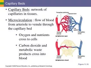
Objective Design a tissue engineering scaffold and supporting microfluidic control system to guide the development of a network of capillary tubes in vitro.
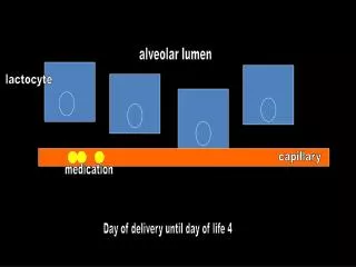
Introduction Bioreactors are commonly used biotechnology equipment in which small organisms and other biological components are grown. In this project, a bioreactor is being used to grow a three dimensional organotypic cell culture comprised of primary endothelial cells and fibroblast embedded in a collagen matrix. This culture has been shown to produce a capillary network. One of the main goals of this project is to show that the growth of this capillary network can be guided using a Matrix Enabled Capillary Scaffold (MECS). Perfusion is then introduced using a microfluidic network so that the cultured cells can receive nutrients and be rid of wastes. The flow of this perfusion network is monitored for pH and oxygen content with a LabView control system. http://www.nyee.edu/images/cartoon2.jpg
Motivation In order to study the functions and mechanisms of a system, scientists commonly use animal models such as mice, rats, and rabbits. However this practice has several shortcomings. Obviously, mice are not people, and though animal studies can provide a reasonable basis to questions, results can often vary between species. An animal system is relatively difficult to manipulate, and much of the control must be done on the molecular level by reconstructing the genome. Lastly, the manipulations frequently can not carry over from one study to another, leading to a redesigning of the entire model. This project is an attempt to overcome these shortcomings by including the following characteristics: Human system Primary human cells Many levels of control Perfusion, pH, oxygen Variety of uses Easy adaptability by changing cell lines or layout of scaffold Simplified model Ideal for disease research, only the relevant tissue included without overall bodily interactions
Culture Layout A new generation organ culture arising from cross-talk between multiple primary human cell types. FASEB Journal, Published online December 2004, M. Martins-Green, Q-J Li, M. Yao An organotypic culture is simply any cell culture that mimics the in vivo tissue in form and function. The organotypic culture in use in this project is adapted from a model used by Manuela Martins-Green at University of California-Riverside. Her culture is comprised of four cell layers as shown above. Our cultures are simpler and contain one less layer, two layers of human dermal fibroblasts embedded in a collagen matrix and separated by a layer of human microvascular endothelial cells. This culture is constructed in a transwell chamber in a normal 12-well culture plate. The culture is fed by placing media below the chamber, allowing it to perfuse upward to the culture through a polycarbonate membrane, as well as being placed on top of the entire culture and seeping downward.
Culture Layout The Martins-Green culture was shown to accurately represent human skin tissue. However, we are currently only interested in the manipulation of the capillary network this culture contains. Cell-culturing work last semester was directed toward verifying the work of Martins-Green. Cross sections taken from our cultures show that a capillary network can indeed arise from such a simple tissue model. Microvessels are around 10um in diameter and are contained within a culture 50um to 150um in thickness. Further work must be done to determine the overall structure of this network, and to fine tune the variables needed in order to reach the desired result. Resemblance of organotypic cultures to human skin, 2004, M. Martins-Green a a a a Cross section of organotypic culture showing microvessel openings
Bioreactor Design Supply Network Support Filter Collagen Capillary Scaffold Collagen Support Filter Supply Network The purpose of the bioreactor is to add another spatial dimension to the transwell plate cocultures. In this design, a scaffold (MECS) is seeded with endothelial cells and is placed between two layers of collagen seeded with fibroblasts. Parallel supply networks above and below perfuse the tissue culture with nutrients via diffusion through supporting nano-pore filters.
Scaffold Design Parameters Representation of Chick Chorioallantoic Membrane (CAM) Vasculature Vasculature of Mouse Ear (L. Nanney, Unpublished) The inspiration for the scaffold design is the fractal pattern of vasculature occurring in nature. Cells grown in fractal flows are exposed to similar nutrient, waste, and shear stress levels. We have developed two designs for the scaffold layer: a PDMS ‘egg crate’ design and a monolithlic collagen design. http://www.nyee.edu/images/cartoon2.jpg
Scaffold Design 1: Collagen Monolith • Design Features: • Endothelial cells placed directly within patterned microchannels of collagen • Fabrication: • PDMS stamp delivers intermediate sacrificial layer of Matrigel • Collagen molded around Matrigel • Matrigel removed by enzyme • Weaknesses: • Difficult to integrate with flow • Less rigid than PDMS Pattern:
Scaffold Design 2: PDMS ‘Egg crate’ • Design Features: • Supports arterial and venous supply in rigid network • Straps connecting the structures allow for cellular communication above and below the network • Fabrication: • 2-Layer SU-8 photolithography to create casting mold • PDMS membrane soft-lithography to create structure • Weaknesses: • Difficult fabrication • Not bio-degradable
Top View – SU-8 Mold Perfect Alignment! Two layer SU-8 photolithography Photolithography/Microfabrication Process for PDMS ‘Egg Crate’ Scaffold
20 um 30 um 30um Capillary Capillary 50 um 190 um Scaffold Dimensions Thick PDMS eggcrate scaffold Cross-Section
Atrial filtration Venous filtration Integration with ‘plumbing’ for flow of nutrients and waste
Overall Superstructure The scaffold and ‘plumbing’ are then connected to the outside world via standardized ports on a glass chip.
Overall fluidics Perfusion of the bioreactor occurs by a fluidics system that both injects media to support the cells, and also maintains stable pH and oxygen levels. Two syringe pumps inject low- and high-pH RPMI media into separate flow lines that unite and feed fluid through an oxygenator. After passing through the bioreactor, the flow line is split and fed into two dedicated output syringes mounted onto the same pumps as the input syringes, so as not to re-use any fluid. Changes in pH are detected by a pH sensor and processed by computer. Appropriate commands are then sent to the syringe pumps to raise or lower pH while keeping flow rate constant.
Flow rate and pH constraints The scale of the device and its accompanying operations is miniscule. The total volume of the bioreactor is on the order of 1-10 ul, with the total flow rate of the fluidics system perhaps reaching 20 ul/hr. Approximately 45,000 fibroblasts and endothelial cells will be inside the bioreactor, with cell media requirements of 0.0004 ul/hr/cell. The desired pH range of the bioreactor is between 7.2 and 7.4, as most cells require such conditions.
Hardware and Software Each of two Harvard Apparatus Pico Plus model syringe pumps has two 500 ul Hamilton syringes mounted on top. One syringe injects fluid into the flow line, while the other takes fluid out of the flow line. Labview 8.0 is used to control the pumps, adjusting their injection and uptake rates based on information from the pH sensor processed using a control theory equation.
Graphs pH ranges PID coefficients pH sensor settings Main Control Program The graphical user interface for the Labview control program allows adjustment of the calibration constants and settings of the pH sensor. Coefficients for the PID control theory equation that processes pH data can also be changed, as can the tolerance ranges for the desired pH of the bioreactor. Graphs display the recent histories of the pump injection rates, the error and control signals, and the bioreactor's pH. The error signal is the difference between the bioreactor's pH and the upper or lower limit of the desired pH range. The control signal is sent to the pumps to reduce the error signal, and is constructed by processing the error signal using the PID control theory equation.
pH data is processed using the Proportional, Integral, Differential (PID) equation C(t) = P*e(t) + I*∫e(t) + D*d[e(t)]/dt The Proportional, Integral, Differential (PID) control theory equation processes the error signal and produces a control signal that is sent to the pumps in order to compensate for deviations from the desired pH range. The three main terms of the equation each make different contributions to the control signal. The proportional term (P) of the equation takes the immediate magnitude of the error and multiplies it by the "P" coefficient, allowing a quick response to the presence of error. The integral term (I) of the equation multiplies the sum of previous values of the error signal by the "I" coefficient, helping to compensate for persistent, steady-state error. The differential term (D) of the equation multiplies the immediate slope of the error signal by the "D" coefficient, helping to compensate for trends in error. By adjusting each term's coefficient, different aspects of the error signal's behavior can be emphasized in constructing the control signal, thereby optimizing that signal to fit the unique characteristics of the system.
Conclusion: Project Goals • Model a complete microvascular network • Support cellular processes • Allow evaluation of molecular mechanisms • Provide environment for endothelial cell differentiation • Facilitate formation of stable tubular structures • Support a flow of perfusate
References • Martins-Green M, Li Q, Yao M. A New Generation Organ Culture Arising from Cross-Talk Between Primary Human Cell Types. Unpublished. • Nanney, Lillian et al. Unpublished research. • Tang MD et al. Fabrication of collagen gels that contain patterned micrometer-scale cavities. Adv. Mater, 2004.