Download

1 / 1
10 likes | 91 Vues
Investigating secondary electron emission from surfaces under ion impact in the SIRAD IEEM setup through experimental measurements and scaling laws. Understanding the relation between electron yield and ion impact for varied materials.

E N D
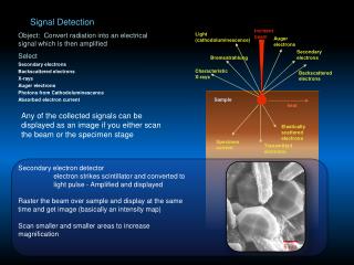
Secondary Electron Emission studies for the SIRAD IEEM Secondary electron emission from a surface by ion impact is a superficial phenomenon that depends on the nature of the surface and on the species and kinetic energy of the impinging ion. The ratio of the average electron yield Y to the surface value of the Linear Energy Transfer LET0 is not constant and a more appropriate account allows toscale with the atomic number Z of the impinging ion: = Y/LET0 = a Z(b-2) where b<2 and a are parameters that characterize the impacted surface. The rationale and physical modeling of the scaling is discussed extensively by Borovsky and Suszeynsky in [6]. The experimental values of the ratio (points) are in good agreement with the scaling laws reported for light ion species at lower ion energies (dashed curves) [6]. The solid curves are fits to the data points. The fitting parameters and errors are: The 15 MV Tandem accelerator of Legnaro (Italy) INFN Laboratory houses an irradiation facility, SIRAD, dedicated to radiation damage studies on semiconductor detectors, electronic devices and systems [1]. Single Event Effect studies are a very important part of the intense experimental program and the global characterization of COTS and ASIC devices and systems for high energy physics and space applications are routinely performed at SIRAD. To extend characterization capabilities to reconstructing the ion impact point with micrometric lateral resolutions the SIRAD group is assembling an Ion-Electron Emission Microscope (IEEM) [2].In an axial IEEM the secondary electrons emitted by the sample during normal ion impact are transferred up through the electron microscope onto a coaxial two-dimensional electron detector. In the SIRAD configuration the basic detector is a micro-channel plate detector (MCP) coupled to a fast phosphor;the photons emitted by the phosphor are then viewed by a high rate photon position sensitive detection system external to the vacuum chamber to obtain the enlarged image of the ion impacted surface [3]. The goal of the secondary electron yield experimental program at SIRAD is to measure the yields from various standard and novel materials and identify good electron emitter materials in the form of thin foils, laminas or membranes to be superimposed to devices for Single Event Effect characterisation using Ion Electron Emission Microscopy. The ion hit detection efficiency of an IEEM strongly depends on the electron yield for single ion impact from the surface of the surface under study. Few measurements of electron yield exist in the few MeV/amu ion energy region typical of SEE facilities such as SIRAD.We here report on measurements performed at SIRAD of the electron yield of Au, Al and B-doped diamond for various ion beams ranging from C (94 MeV) to Ag (272 MeV), typical of the SIRAD facility. The ion species, the kinetic energies used and the Linear Energy Transfer values in the various targets are reported in the following table. Targets: aluminium foil, three gold targets (one bulk and two gold depositions, 70 m/cm2 and 200 m/cm2, on mylar) and three B-doped diamond samples furnished by Bernd Fischer and Marian Cholewa of GSI single ion microbeam group with boron concentrations in the 50-500 ppm range [4][5]. On the basis of the scaling laws one may calculate the average secondary electron yields from gold and aluminum for any ion once the LET0 value of the ion in the target material is known [7]. In particular one may then estimate the ion detection efficiency of and axial IEEM. Theefficiencies shown in the adjacent figure were calculated for ions in typical accelerator conditions; e.g. a TANDEM voltage of 14 MV. The electron yield from the doped diamond lamina was initially a factor two higher than that obtained from gold, confirming measurements performed at GSI in a single ion impact mode. This is important because it extends the IEEM ion impact detection efficiency to light ions. As the experiment progressed we observed a progressive decrease in the yield respect to gold in the diamond samples: from the initial value two the diamond the ratio dropped 100%. One diamond sample was then further irradiated with the 28Si 158 MeV beam for several hours and the yield was continuously monitored. The drop in yield is significant only after very high fluence values (>1013 ions/cm2). Measurements were performed using a special Faraday cup system schematically shown in the figure: The ion beams, with typical currents in the 10-25 nA range, were first focused to obtain a 3-4 mm spot on an alumina scintillator on the sample holder. The chosen target was then moved into position. The target current was initially measured with a collector voltage of –100 V. The collector voltage was then slowly ramped up to 100 V, typically in 200 steps of 1 Volt steps per second. The currents on the target and collector were measured with a precision multi-source pico-ammeter (HP 4142 B). The secondary electrons emitted by the target, electrically grounded, were suppressed (e.g. in the normal Faraday mode to give the true beam current), or collected by an independent collecting electrode, depending on the voltage polarity of the collector. The yield is given by the relation Y = Q I/Ibeam where I is thenet change in target current in going from full suppression to full collection and Q is the electric charge of the impinging ion (see table and adjacent figure).The collector current behaviour mirrors the target current and was used as a consistency check. The uncertainty in the picoammeter and voltage supply is negligible compared to the dominant uncertainty, of the order of a few percent, in establishing the plateau levels in the current VS collector voltage curves. The initial beam was 28Si with E=158 MeV and Q=11. The figure of the left reports the measured yields. The hatched columns are the yields obtained measuring the target current. The collector currents (not hatched columns) give consistent values.