HIAPER Data Acquisition System: Overview and Architecture
210 likes | 324 Vues
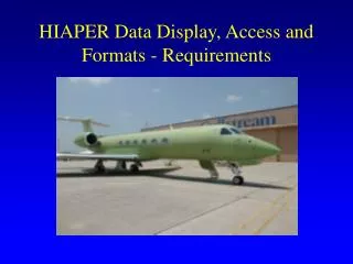
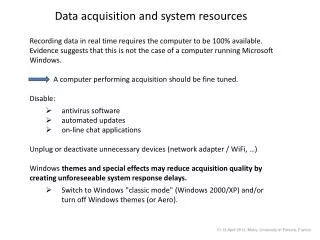
The HIAPER Data Acquisition System offers real-time data acquisition, processing, and display capabilities for research aircraft. Its distributed sampling modules (DSM) and industry-standard architecture ensure reliable performance. The system is designed to minimize weight, size, and power while providing flexibility and remote access features for operating in external environments. Supporting various data inputs, the system includes robust hardware components and communication interfaces for seamless data handling.

HIAPER Data Acquisition System: Overview and Architecture
E N D
Presentation Transcript
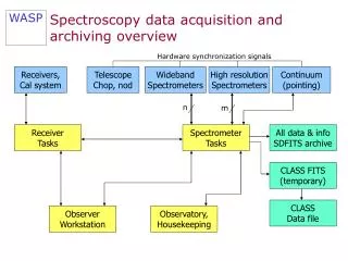
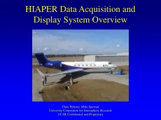
HIAPER Data Acquisition and Display System Overview Chris Webster, Mike Spowart University Corporation for Atmospheric Research UCAR Confidential and Proprietary
Other Systems (2003) • University of Wyoming • Single computer 6U VME • NOAA • P3 uses vacuum tubes, GIV has RAF system • Working on a new data system • CIRPAS • Distributed National Instruments with Labview display • SATCOM • NASA DC-8 • small system for internal use only
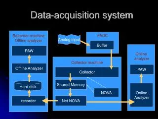
System Architecture; Data Flow Onboard Data Server Transmit UDP to ground sql database DSM Data Logger UDP Broadcast DSM Onboard Display(s) Processor (time-series & 2d) Raw Data Inputs - Analog - Digital - Serial Onboard Display(s) SQL Database Real-time updates Historical data Data Acquisition and Recording Data Processing and Display
HIAPER Data Acquisition System Introduction • Minimize weight, size, and power. • Flexible, large number of standard interfaces, limited custom interfaces. • Suitable to G-V external operating environment. • Capable of operating unattended during flight, including take-off and landing. • Remote access to data system and network connected instruments provided by satellite communications.
Overview • Small distributed sampling modules (DSM). • Industry standard PC104 DSM architecture (ISA bus). • COTS hardware for digital interfaces. • Custom over sampling Sigma/Delta A/D converter with digital FIR filters. • Eventually replace ADS II in NCAR C-130 and NRL P3 aircraft (ADS III?).
Description • DSMs connected to host computer via local area network. • Host computer includes redundant CPUs, internal disks, power supplies, and dual external removable disk data recorders. • Raw data recorded in binary format backward compatible with present ADS-II. • Seven card PC-104 enclosure. Includes one slot for power supply, one for CPU, and one for timing card. • Up to 4 instrument interface cards in one DSM. • 5 ½ x 5 ½ x L.
Requirements • Digital data collection: • Serial data: • 11 channels asynchronous RS-232, RS-422, RS-485 up to 115K baud. • USB 1.1 host control, 2 channels for PMS-2D, ~ 200K bytes/sec. • ARINC-429 12.5K and 100K baud, 4 Rx, 2 Tx. • Programmable logic provided for ease of implementing bi-phase, APN-232, etc. Anything I/O card. • Parallel data: • Flexible 32-bit bi-directional bus with strobes. Configurable as 1x, 4x, 8x, 16x, and 32 bits. Anything I/O card. • Pulse counters: • 16-bits, double buffered with strobes. Anything I/O card.
Requirements Contd. • Computation: • Host PC control computer running Linux. • DSM processor running RTLinux. • Host control computer records data, runs instrument control program, interfaces to satcom, and runs data processing and local display programs. • Communications and Control: • 100baseT CAT-6 Ethernet data LAN (expandable to 1 GHz). • GUI soft-key programmable instrument control program via host control computer.
Requirements Contd. • Time Synchronization and Distribution: • GPS time-of-day distributed to DSMs via IRIG-B network from the time server. • GPS 1PPS signal distributed to all DSMs. • GPS time-of-day distributed via NTP. • Display: • Data recording, processing and display programs to run on host PC.
Hardware • Arcom Viper CPU (PDA): • Intel XScale 400 MHz processor. • 1.4W max. power dissipation. • -40° C to +85° C operating temp. range option. • 64M bytes RAM. • 256K bytes battery backed SRAM. • 10/100baseT Ethernet. • Dual USB ports (DSM console?). • 5 serial ports >= 230.4K baud(4 RS-232, 1 RS-422/485). • Jxi2, inc., IRIG-B time/frequency processor: • Multiple time code formats (IRIG-A, IRIG-B, DC Level Shift, etc.). • Three user selectable pulse outputs, 1 Hz – 1.5 MHz. • One “heartbeat” bus interrupt. • GPS 1 PPS input synchronization with internal clock, 10 MHz oscillator. • Power Supply: • +5, +/- 12 VDC PC-104 card AC-to-DC converter.
Network topology data-net Iridium-net display-net Inmarsat SATCOM DataServer DSM Display DSM TimeServer IRIG & NTP Display DSM DSM self-recordinginstrument
System Architecture; Data Flow Onboard Data Server Transmit UDP to ground sql database DSM Data Logger UDP Broadcast DSM Onboard Display(s) Processor (time-series & 2d) Raw Data Inputs - Analog - Digital - Serial Onboard Display(s) SQL Database Real-time updates Historical data Data Acquisition and Recording Data Processing and Display
Display System Architecture Onboard Server Raw Data Image Data Onboard Display(s) Processor (e.g. MCR) UDP Processor (time-series & 2d) UDP Broadcast Imaging (e.g. AIMR) netCDF (HRT) SQL (LRT) “Smart” Instruments SATCOM (on ground) QC Display(s) Video titling
Access to Data - onboard • ASCII data feeds of scalar time-series • Network UDP broadcast • Multiple and configurable • Serial feed; Digi SP-One (converts UDP to RS232) • SQL Database/repository • Network read-writable by anyone • has permissions control • easy to use and very common
Display Program • Portable (Windows, Linux & Mac) with ease of total install. Qt for GUI, Qwt for plotting. • As near real-time as possible (current delay is ~2.5 seconds from DAQ to display). • “standard” displays should cover all obvious and current time-series plots and RAF facility instruments. • Real-time & Post-processing
“Standard” display types • Time-series • XY & flight track • ASCII • lists • Fixed • QC • Histograms • PMS-2D • Skew-T • Imager which can handle “scans” as defined • Video (ftp direct to camera for RT). • GIF/PNG/JPG viewer
Quality Control/Check (QC) • Range check • Spike detection • Flat-line detection • Level shift
Display Hardware • Commodity rack mount (vs. built in) • Take advantage of latest technology • Laptop still best solution • Battery = UPS • Thin & light • Wireless notepad computers?