Field Effect Transistors: Types, Structures, and Characteristics
500 likes | 836 Vues
Explore Field Effect Transistors (FETs) and their types (JFET, MOSFET), structures, and characteristics, such as linear region operation, output resistance, and channel modulation. Discover NMOS and PMOS transistors and their applications in integrated circuits with practical examples. Dive into the world of FET electronics with an in-depth overview.

Field Effect Transistors: Types, Structures, and Characteristics
E N D
Presentation Transcript
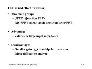
FIELD EFFECT TRANSISTORS(FET) Celso José Faria de Araújo, Dr.
FET X BJT (NPN) Drain Collector Gate Base Source Emitter • FET • 3 terminal device • Channel e- current from source to drain controlled by the electric field generated by the gate • Extremely high input impedance for base • BJT • 3 terminal device emitter to collector e- current controlled by the current injected into the base Field Effect Transistors Electronics – Celso José Faria de Araújo, M.Sc.
Types of FETs npn npn Depletion mode junction FETs (JFET) pnp pnp Metal oxide semi-conductor FET (MOSFET) • In addition to carrier type (N or P channel), there are differences in • how the control element is constructed (Junction x Insulated) and • those devices must be used differently • depletion/enhancement mode • enhancement mode (insulated gate FETs, IGFETs, are the same as MOSFETs) Field Effect Transistors Electronics – Celso José Faria de Araújo, M.Sc.
Physical structure of the enhancement-type NMOS transistor: (a) perspective view; (b) cross section. Typically L = 1 to 10 m, W = 2 to 500 m, and the thickness of the oxide layer is in the range of 0.02 to 0.1 m. Field Effect Transistors Electronics – Celso José Faria de Araújo, M.Sc.
Waterfalls analogy Water ( a ) MOSFET in the linear region ( b ) MOSFET with channel just pinched off at the drain. ( c ) Channel pinch off for vDS > vGS - VTN Field Effect Transistors Electronics – Celso José Faria de Araújo, M.Sc.
The enhancement-type NMOS transistor with a positive voltage applied to the gate. An n channel is induced at the top of the substrate beneath the gate. Field Effect Transistors Electronics – Celso José Faria de Araújo, M.Sc.
An NMOS transistor with vGS > Vtand with a small vDS applied. The device acts as a conductance whose value is determined by vGS. Specifically, the channel conductance is proportional to vGS - Vt, and this iD is proportional to (vGS - Vt) vDS. Note that the depletion region is not shown (for simplicity). Field Effect Transistors Electronics – Celso José Faria de Araújo, M.Sc.
Linear Region (small vDS) vGS Vtn 0 vDS vDSSAT= vGS-Vtn VTN =1V Field Effect Transistors Electronics – Celso José Faria de Araújo, M.Sc.
Operation of the enhancement NMOS transistor as vDS is increased. The induced channel acquires a tapered shape and its resistance increases as vDS is increased. Here, vGS is kept constant at a value > Vt. Field Effect Transistors Electronics – Celso José Faria de Araújo, M.Sc.
The drain current iD versus the drain-to-source voltage vDS for an enhancement-type NMOS transistor operated with vGS > Vt. Field Effect Transistors Electronics – Celso José Faria de Araújo, M.Sc.
Output characteristicsfor an NMOS transistor withVtn = 1 V and k’n (W/L)= 25 x 10-6 A/V2 vD vS Field Effect Transistors Electronics – Celso José Faria de Araújo, M.Sc.
Derivation of the iD - vDS characteristic of the NMOS transistor. Field Effect Transistors Electronics – Celso José Faria de Araújo, M.Sc.
The PMOS Transistor Field Effect Transistors Electronics – Celso José Faria de Araújo, M.Sc.
Output characteristics for a PMOS transistor withVtp = -1V and k’P (W/L)= 25 x 10-6 A/V2 vS vD Field Effect Transistors Electronics – Celso José Faria de Araújo, M.Sc.
Cross section of a CMOS integrated circuit. Note that the PMOS transistor is formed in a separate n-type region, known as an n well. Another arrangement is also possible in which an n-type body is used and the n device is formed in a p well. Field Effect Transistors Electronics – Celso José Faria de Araújo, M.Sc.
(a) An n-channel enhancement-type MOSFET with vGSand vDSapplied and with the normal directions of current flow indicated. (b)The iD - vDS characteristics for a device with Vt = 1 V and k’n(W/L) = 0.5 mA/V2 (d) The iD - vGS characteristic for an enhancement-type NMOS transistor in saturation. (d) Field Effect Transistors Electronics – Celso José Faria de Araújo, M.Sc.
Channel Length Modulation LM Increasing vDSbeyond vDSsat causes the channel pinch-off point to move slightly away from the drain, thus reducing the effective channel length (by L). Field Effect Transistors Electronics – Celso José Faria de Araújo, M.Sc.
Effect of vDS on iD in the saturation region. The MOSFET parameter VAis typically in the range of 30 to 200 V. Output Resistance: VAis directly proportional to L; thus two devices with the same process, and having channel lengths L1 e L2, will have Early voltage VA1 and VA2,. Field Effect Transistors Electronics – Celso José Faria de Araújo, M.Sc.
Large-signal equivalent circuit model of the n-channel MOSFET in saturation, incorporating the output resistance ro. The output resistance models the linear dependence of iDon vDS and is given by roVA/ID. Field Effect Transistors Electronics – Celso José Faria de Araújo, M.Sc.
Summary of equations for the enhancement-mode MOSFET P-channel N-channel or or Vtp < 0 vDS 0 Vtn > 0 vDS 0 Field Effect Transistors Electronics – Celso José Faria de Araújo, M.Sc.
The current-voltage characteristics of a depletion-type n-channel MOSFET for which Vt = -4 V and k’n(W/L) = 2 mA/V2: (a) transistor with current and voltage polarities indicated; (b) the iD - vDS characteristics; (c) the iD - vGS characteristic in saturation. Field Effect Transistors Electronics – Celso José Faria de Araújo, M.Sc.
Bias Circuits 1 • usually neglected ( 1/ =VA) • Q-point most often located in saturation for analog circuits ( assuming the MOSFET to be in the saturation region ) ( two solutions only one is possible ) Ex: VDD = 10 V R1 = 150 kR2 = 100 kRS = 10k RD = 50k k’n(W/L) = 50A/V2 Vt = 1 V Solution: ID = 100A VDS = 4 V Field Effect Transistors Electronics – Celso José Faria de Araújo, M.Sc.
Bias Circuits 2 V / R DD D load line curve V = V DS GS V GS1 Q V GS2 V GS3 V V = V DD DS GS2 Analysis Two power supplies are available A simple circuit utilizing a current source Field Effect Transistors Electronics – Celso José Faria de Araújo, M.Sc.
Basic MOSFET current mirror. Example: VDD = 5V ;IREF=10A; Q1and Q2are matched ; L=10 m and W=100 m; Vt = 1V ; k’n=20 A/V2 VA = 10L; Vo=+3V Q1: I V converter Q2: V I converter If Q2 in saturation then Field Effect Transistors Electronics – Celso José Faria de Araújo, M.Sc.
The operation of the MOSFET as an amplifier. Field Effect Transistors Electronics – Celso José Faria de Araújo, M.Sc.
Small-signal models for the MOSFET: (a) neglecting the dependence of iD on vDS in saturation (channel-length modulation effect); and (b) including the effect of channel-length modulation modeled by output resistance ro = |VA|/ID. (b.1) -Model (a.1) -Model (a.2) T-Model (b.2) T-Model Field Effect Transistors Electronics – Celso José Faria de Araújo, M.Sc.
Example: Vt = 1.5V ; k’n(W/L)=0.25 mA/V2 VA = 50V Field Effect Transistors Electronics – Celso José Faria de Araújo, M.Sc.
Small-signal equivalent-circuit model of a MOSFET in which the body is not connected to the source. Field Effect Transistors Electronics – Celso José Faria de Araújo, M.Sc.
Basic amplifier configurations with current sources Source follower or common-drain amplifier Common-source amplifier Common-gate amplifier Field Effect Transistors Electronics – Celso José Faria de Araújo, M.Sc.
The CMOS common-source amplifier: (a) circuit; (b)i-v characteristic of the active-load Q2; (c) graphical construction to determine the transfer characteristic; and transfer characteristic. ID2 ID2 Field Effect Transistors Electronics – Celso José Faria de Araújo, M.Sc.
Example: VDD=10V;Vtn = | Vtp| = 1V ; k’n= 2 k’p= 20 A/V2(W=100 m; L =10 m |VA|= 100V for both the n and p device)IREF=100 A. Field Effect Transistors Electronics – Celso José Faria de Araújo, M.Sc.
The CMOS common-gate amplifier: (a) circuit; (b) small-signal equivalent circuit; and (c) simplified version of the circuit in (b). Field Effect Transistors Electronics – Celso José Faria de Araújo, M.Sc.
The source follower: (a) circuit; (b) small-signal equivalent circuit; and (c) simplified version of the equivalent circuit. Field Effect Transistors Electronics – Celso José Faria de Araújo, M.Sc.
(a) NMOS amplifier with enhancement load; (b) graphical determination of the transfer characteristic; (c) transfer characteristic. Field Effect Transistors Electronics – Celso José Faria de Araújo, M.Sc.
The NMOS amplifier with depletion load: (a) circuit; (b) graphical construction to determine the transfer characteristic; and (c) transfer characteristic. Field Effect Transistors Electronics – Celso José Faria de Araújo, M.Sc.
Operation of the CMOS inverter when v1 is high: (a) circuit with v1 = VDD (logic-1 level, or VOH); (b) graphical construction to determine the operating point; and (c) equivalent circuit. Field Effect Transistors Electronics – Celso José Faria de Araújo, M.Sc.
Operation of the CMOS inverter when v1 is low: (a) circuit with v1 = 0V (logic-0 level, or VOL); (b) graphical construction to determine the operating point; and (c) equivalent circuit. Field Effect Transistors Electronics – Celso José Faria de Araújo, M.Sc.
The voltage transfer characteristic of the CMOS inverter. Field Effect Transistors Electronics – Celso José Faria de Araújo, M.Sc.
Dynamic operation of a capacitively loaded CMOS inverter: (a) circuit; (b) input and output waveforms; (c) trajectory of the operating point as the input goes high and C discharges through the QN; (d) equivalent circuit during the capacitor discharge. Field Effect Transistors Electronics – Celso José Faria de Araújo, M.Sc.
(a) High-frequency equivalent circuit model for the MOSFET; (b) the equivalent circuit for the case the source is connected to the substrate (body); (c) the equivalent circuit model of (b) with Cdb neglected (to simplify analysis). Strong inversion and saturation: VGS – Vt > 200 mV Field Effect Transistors Electronics – Celso José Faria de Araújo, M.Sc.
Determining the short-circuit current gain Io/Ii. For physical frequencies s = j, it cam be seen that the magnitude of the current gain becomes unity at the frequency: Field Effect Transistors Electronics – Celso José Faria de Araújo, M.Sc.
The Junction Field-Effect Transistor ( a ) JFET with zero gate-source bias ( b ) JFET with negative gate-source voltage that is less negative than the pinch-off voltage VP. Note W’ < W ( c ) JFET at pinch-off with VGS = VP Field Effect Transistors Electronics – Celso José Faria de Araújo, M.Sc.
The Junction Field-Effect Transistor ( a ) JFET with small drain-source ( b ) JFET with channel just at pinch-off with vDS = vDSP ( a ) JFET with small drain-source ( b ) JFET with channel just at pinch-off with vDS = vDSP Field Effect Transistors Electronics – Celso José Faria de Araújo, M.Sc.
Summary of equations for the JFET P-channel N-channel Field Effect Transistors Electronics – Celso José Faria de Araújo, M.Sc.
Output characteristics for a JFET with IDSS = 200 A and VP = -4V Field Effect Transistors Electronics – Celso José Faria de Araújo, M.Sc.
Transfer characteristic for a saturated JFET with IDSS = 1 mA and VP = -3.5V Field Effect Transistors Electronics – Celso José Faria de Araújo, M.Sc.
When to use JFETs • JFET have much higher input impedances and much lower input currents than BJTs. • BJTs are more linear than JFETs. • The gain of a BJT is much higher than that of a JFET. Field Effect Transistors Electronics – Celso José Faria de Araújo, M.Sc.
JFET (Example) The JFET in the circuit below has VP=-3V, IDSS=9mA, and =0. Find the values of all resistors so that VG=5V, ID=4mA, and VD=11V. Design for 0.05mA in the voltage divider. For the JFET circuit designed in the former exercise, let an input signal vi be capacitively coupled to the gate, a large bypass capacitor be connected between the source and ground, and the output signal vo be taken from the drain through a large coupling capacitor. The resulting common-source amplifier is shown below. Calculate gm and ro (assuming VA=100V). Also find Ri and Ro. Field Effect Transistors Electronics – Celso José Faria de Araújo, M.Sc.
References • SEDRA. Adel S. e SMITH, Kenneth C. Microelectronic Circuits. Oxford University Press. • BOYLESTAD, Robert e NASHELSKY, Louis. Dispositivos Eletrônicos e Teoria de Circuitos. Prentice Hall do Brasil. • SZE, S. M. Physics of Semiconductor Devices. John Wiley & Sons. • SCHILLING, Donald L. e BELOVE, Charles. Circuitos Eletrônicos Discretos e Integrados. Guanabara Dois. • COMER, David J. Introduction to Semiconductor Circuits Design. Addison Wesley Publishing Company. • MALVINO, Albert P. Eletrônica. Volume I. McGraw-Hill. Field Effect Transistors Electronics – Celso José Faria de Araújo, M.Sc.