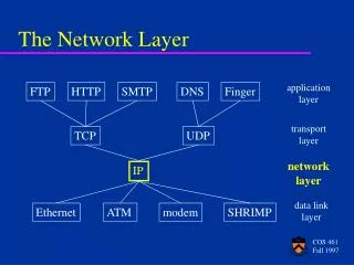
The Network Layer in the Internet
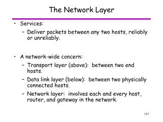
390 likes | 588 Vues
The Network Layer in the Internet. Overview. Internet Intro The IP Protocol IP Addresses Subnets Internet Control Protocols CIDR – Classless InterDomain Routing IPv6. Internet Intro.

The Network Layer in the Internet
E N D
Presentation Transcript
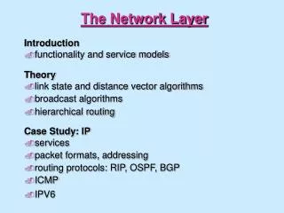
Overview • Internet Intro • The IP Protocol • IP Addresses • Subnets • Internet Control Protocols • CIDR – Classless InterDomain Routing • IPv6
Internet Intro • At the network layer, the Internet can be viewed as a collection of subnetworks or Autonomous Systems (AS) that are connected together. • There is no real structure, but several major backbones exist. These are constructed from high-bandwidth lines and fast routers. • Attached to the backbones are regional (midlevel) networks, and attached to these regional networks are the LANs at many universities, companies and Internet service providers.
Internet Intro • A sketch of this semi-hierarchical organization is given below:
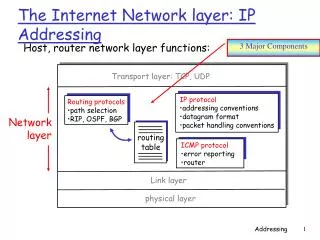
Internet Intro • The glue that holds the Internet together is the network layer protocol, IP (Internet Protocol). • Unlike most older network layer protocols, it was designed from the beginning with internetworking in mind. • A good way to think of the network layer is this: its job is to provide a best-effort way to transport datagrams (packets) from source to destination, without regard to whether or not these machines are on the same network, or whether or not there are other networks in the between them.
Internet Intro • Datagram – in the context of the internal operations of the subnet, a connection is usually called a virtual circuit (in analogy with the physical circuits set up by the telephone system). The independent packets of the connectionless organization are called datagrams, in analogy with telegrams.
Internet Intro • Communication in the Internet works as follows: • The transport layer takes data streams and breaks them up into datagrams. • In theory datagrams can be up to 64KB each, but in practice they are usually around 1500bytes. Each datagram is transmitted through the Internet, possibly being fragmented into smaller units as it goes. • When all the pieces finally get to the destination machine, they are reassembled by the network layer into the original datagram. • This datagram is then handed to the transport layer, which inserts it into the receiving process’ input stream.
The IP Protocol • An appropriate place to start our study of the network layer in the Internet is the format of the IP datagrams themselves. • An IP datagram consists of: • a header part and • a data/text part • The header has a 20-byte fixed part and a variable length optional part.
The IP Protocol Header Fig. 1. The IP (Internet Protocol) header
The IP Protocol • The Version field keeps track of which version of the protocol the datagram belongs to. • Since the header length is not constant, a field in the header, called IHL, is provided to tell how long the header is, in 32 bit words. (min 5, max 15) • The type of service field allows the host to tell the subnet what kind of service it wants. (various combinations of reliability and speed are possible) • The total length includes everything in the datagram – both header and data. The maximum length is 65,535 bytes.
The IP Protocol • The identification field is needed to allow the destination host to determine which datagram a newly arrived fragment belongs to. All the fragments of a datagram contain the same Identification value. • Next comes an unused bit, and then two 1-bit fields: • DF stands for Don’t Fragment - it is an order to the routers not to fragment the packet, because the destination is incapable of putting the pieces back together • MF stands for More Fragments - all fragments except the last one have this bit set. It is needed to know when all fragments of a datagram have arrived.
The IP Protocol • The Fragment offset tells where in the current datagram this fragment belongs. • The Time to live field is a counter used to limit packet lifetimes. It is supposed to count time in seconds, allowing maximum lifetime of 255 sec. It must be decremented on each hop. When it hits 0, the packet is discarded and a warning packet is sent back to the source host. This feature prevents datagrams from wondering around forever. • When the network layer has assembled a complete datagram, it needs to know what to do with it. The Protocol field tells it which transport process to give it to. TCP is one possibility, but so are UDP and some others. The numbering of protocols is standard across the entire Internet.
The IP Protocol • The Header checksum verifies the header. It is useful for detecting errors generated by bad memory words inside a router. • The Source address and Destination address indicate the network number and host number. We will discuss Internet addresses in the next section. • The Options field was designed to provide an escape to allow subsequent versions of the protocol to include information not present in the original design, and to permit experimenters to try new ideas. The options are variable length. Currently 5 options are defined:
The IP Protocol Fig. 2. IP options
IP Addresses • Every host and router on the Internet has an IP address, which encodes its network number and host number. • The combination is unique: no two machines have the same IP address. • All IP addresses are 32 bits long and are used in the Source address and Destination address of IP packets. • Those machines that connect to multiple networks have a different IP address on each network.
IP Addresses • The formats used for IP addresses are shown below: Fig. 3. IP address formats
IP Addresses • The classes allow for the following number of networks/hosts each: • A – up to 126 networks (e.g. LANs) with 16 million hosts each • B – 16,382 (214) networks with up to 64K hosts • C – 2 million networks with up to 254 hosts each • D – multicast, in which a datagram is directed to multiple hosts • E – addresses beginning with 11110 are reserved for future use
IP Addresses • Tens of thousands of networks are now connected to the Internet, and the number doubles every year. • Network numbers are assigned by the NIC (Network Information Center) to avoid conflicts • Network addresses, which are 32-bit numbers, are usually written in dotted decimal notation. • In this format, each of the 4 bytes is written in decimal – from 0 to 255. For example 192.41.6.20 . The lowest IP address is 0.0.0.0 and the highest is 255.255.255.255 .
IP Addresses Fig. 4. Special IP addresses
Subnets • As we have seen, all the hosts in a network must have the same network number. This property of IP addressing can cause problems as networks grow. • For example, consider a company that stars out with one class C LAN on the Internet. As time goes on, it might acquire more than 254 machines, and thus need a second class C address. Eventually, it might end up with many LANs, each with its own router and each with its own class C network number. • Every time a new network is installed the system administrator has to contact NIC to get a new network number. Then this number must be announced to the world.
Subnets • The solution to these problems is to allow a network to be split into several parts for internal use, but still act like a single network to the outside world. In the Internet literature, these parts are called subnets. • So, if our growing company started up with a class B address instead of a class C address, it could start out just numbering the hosts from 1 to 254. When the second LAN arrived, it could decide, for example to split the 16-bit host number into a 6 bit subnet number and a 10-bit host number, as shown below: • This split allows 62 LANs, each with up to 1022 hosts. Fig. 5. One of the ways to subnet a class B network
Subnets • Outside the network, the subnetting is not visible, so allocating a new subnet does not require contacting contacting NIC or changing any external databases. • In our example, the first subnet might use IP addresses starting at 130.50.4.1, the second subnet might start at 130.50.8.1, and so on. • To see how subnets work, it is necessary to explain how IP packets are processed at a router.
Subnets/Router processing • Each router has a table listing some number of (network, 0) IP addresses and (this-network, host) IP addresses. The first kind tells how to get to distant networks. The second kind tells how to get to local hosts. Associated with each table is the network interface to use to reach the destination, and certain other information. When an IP packet arrives, its destination address is looked up in the routing table. • If the packet is for a distant network, it is forwarded to the next router on the interface given in the table. • If it is a local host (e.g., on the router’s LAN), it is sent directly to the destination.
Subnets/Router processing • If the network is not present, the packet is forwarded to a default router (gateway) with more extensive tables. • This algorithm means that each router only has to keep track of other networks and local hosts, and not complete (network, host) pairs, which is greatly reducing the size of the the routing table. • When subnetting is introduced, the routing tables are changed, adding entries of the form (this-network, subnet, 0) and (this-network, this-subnet, host). • Thus a router on subnet k knows how to get to all the other subnets and also how to get to all hosts on subnet k . It does not have to know the details about hosts on other subnets.
Subnets/Router processing • In fact, all that needs to be changed is to have each router do a Boolean AND, with the network’s subnet mask (shown on Fig.5.) to get rid of the host number. Next, look up the resulting address in its tables (after determining which network class it is). • For example, a packet addressed to 130.50.15.6 and arriving at a router on subnet 5 is AND-ed with the subnet mask on Fig.5. to give the address 130.50.12.0 . This address is then looked up in the routing table to find out it is on subnet 3, and how to forward it there. The router on subnet 5 is thus spared of the work of keeping track of the addresses of hosts which are not on subnet 5.
Internet Control Protocols • In addition to IP, which is used for data transfer, the Internet has several control protocols used in the network layer, including: • ICMP (Internet Control Message Protocol) • ARP (Address Resolution Protocol) • RARP (Reverse Address Resolution Protocol) and • BOOTP (Bootstrap Protocol)
Internet Control Protocols - ICMP • The operation of the Internet is monitored closely by the routers. When something unexpected occurs, the event is reported by the ICMP (Internet Control Message Protocol), which is also used to test the Internet. • About a dozen types of ICMP messages are defined. The most important ones are listed in Fig. 6. Each ICMP message is encapsulated in an IP packet.
Internet Control Protocols - ICMP Fig. 6. The principal ICMP message types
Internet Control Protocols - ARP • Although every machine on the Internet has one (or more) IP addresses, these cannot be used for sending packets because the data link layer hardware does not understand Internet addresses. • Nowadays, most hosts are attached to a LAN by a network interface/card that only understands LAN addresses. For example, every Ethernet card ever manufactured comes equipped with a 48-bit Ethernet address. Manufacturers of Ethernet cards request a block of addresses from a central authority to ensure that no two cards have the same address (to avoid conflicts). The cards send and receive frames based on this 48-bit Ethernet address. They know nothing at all about 32-bit IP addresses.
Internet Control Protocols - ARP • How do IP addresses get mapped onto data link layer addresses? • One solution is for a host 1 to output a broadcast packet onto the Ethernet asking: “Who owns IP address x.y.z.23 ?” The broadcast will arrive at every machine on Ethernet x.y.z.0, and each one will check its IP address. The host 2, with IP address x.y.z.23, will respond with its Ethernet address, let’s say E2. • The protocol for asking this question and getting the reply is called ARP (Address Resolution Protocol).
Internet Control Protocols - RARP • ARP solves the problem of finding out which Ethernet address corresponds to a given IP address. But sometimes the reverse problem needs to be solved – given an Ethernet address, what is the corresponding IP address? • The RARP (Reverse Address Resolution Protocol) addresses this issue. • This protocol allows for a newly booted workstation to broadcast its Ethernet address and say: “My 48-bit Ethernet address is: 14.04.05.18.01.25. Does anyone out there know my IP address?” The RARP server sees this request, looks up the Ethernet address in its configuration files, and sends back the corresponding IP address.
CIDR – Classless InterDomain Routing • Unfortunately, IP is rapidly becoming a victim of its own popularity: it is running out of addresses. This looming disaster has sparked a great deal of discussion and controversy within the Internet community for what to do about it. • The problem, simply stated, is that the Internet is rapidly running out of IP addresses. • In principle, over 2 billion addresses exist, but the practice of organizing the address space by classes (as shown on Fig. 3.), wastes millions of them.
CIDR – Classless InterDomain Routing • In particular, the real villain is the class B network. For most organizations, a class A network, with 16 million addresses is too big, and a class C network, with 256 addresses is too small. A class B network, with 65,536, is just right. In Internet folklore, this situation is known as the three bears problem. • In reality, a class B address is far too large for most organizations. Studies have shown that more than half of all class B networks have fewer than 50 hosts. A class C network would have done the job, but no doubt every organization that asked for a class B address thought that one day it would outgrow the 8-bit host field. There are 2 million of class C addresses available v.s. only 16,384 class B. • Several solutions have been suggested which solve one problem, but create a new one.
CIDR – Classless InterDomain Routing • One solution that is now being implemented and which will give the Internet a bit of extra breathing room is CIDR (Classless InterDomain Routing). • The basic idea is to allocate the remaining class C networks, of which there are almost 2 million, in variable-sized blocks. If a site needs, say 2000 addresses, it is given a block of 2048 addresses (8 continuous class C networks), and not a full class B address. • The world was partitioned into four zones, and each one given a portion of the class C address space: • Addresses 194.0.0.0 to 195.255.255.255 are for Europe • Addresses 198.0.0.0 to 199. 255.255.255 are for North America • Addresses 200.0.0.0 to 201.255.255.255 are for Central and South America • Addresses 202.0.0.0 to 203.255.255.255 are for Asia and the Pacific
IPv6 • While CIDR may buy a few More years’ time, everyone realizes that the days of IP in its current version (IPv4) are numbered. • In 1990, the IETF (Internet Engineering Task Force) started to work on a new version of IP, one which would never run out of IP addresses, would solve a variety of other problems, and be more flexible and efficient as well. Some of its major goals were to: • Support billions of hosts, even with inefficient address space allocation • Reduce the size of routing tables • Simplify the protocol, to allow routers to process packets faster • Provide better security (authentication and privacy) • Pay more attention to type of service, particularly for real-time data • Allow the protocol to evolve in the future
IPv6 • The IETF issued a call for proposals, and by 1993 a proposal by Deering and Francis was selected, which meets the goals fairly well, and given the designation IPv6. • The IPv6 uses a 128 bit address v.s. 32 bit. A new notation has been devised for these addresses, and they are written as 8 groups of 4 hexadecimal digits with colons between the groups, like this: 8000:0000:0000:0000:0123:4567:89AB:CDEF • Perhaps it is unnecessary to be explicit about it, but there are a lot of 128 bit addresses. Specifically, there are 2128 of them. If the entire earth, land, and water were covered with computers, IPv6 would allow 7x10²³ IP addresses per square meter. While it is not the intention to give every molecule on the surface of the earth its own IP address, we are not that far off.