Chapter 6: Bernoulli and energy equations
3.63k likes | 8.79k Vues
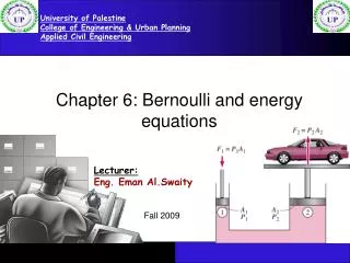
University of Palestine College of Engineering & Urban Planning Applied Civil Engineering. Chapter 6: Bernoulli and energy equations. Lecturer: Eng. Eman Al.Swaity. Fall 2009. OBJECTIVES. Derive the Bernoulli (energy) equation.

Chapter 6: Bernoulli and energy equations
E N D
Presentation Transcript
University of Palestine College of Engineering & Urban Planning Applied Civil Engineering Chapter 6: Bernoulli and energy equations Lecturer: Eng. Eman Al.Swaity Fall 2009
OBJECTIVES • Derive the Bernoulli (energy) equation. • Demonstrate practical uses of the Bernoulli and continuity equation in the analysis of flow. • understand the use of hydraulic and energy grade lines. • Apply Bernoulli Equation to solve fluid mechanics problems (e.g. flow measurement). Chapter 6: Bernoulli and energy equations EGGD3109 Fluid Mechanics
The Bernoulli Equation • Let us first derive the Bernoulli equation, which is one of the most well-known equations of motion in fluid mechanics, and yet is often misused. It is thus important to understand its limitations, and the assumptions made in the derivation. • The assumptions can be summarized as follows: • Inviscid flow (ideal fluid, frictionless) • Steady flow (unsteady Bernoulli equation will not be discussed in this course) • Applied along a streamline • Constant density (incompressible flow) • No shaft work or heat transfer Chapter 6: Bernoulli and energy equations EGGD3109 Fluid Mechanics
The Bernoulli Equation Limitations Chapter 6: Bernoulli and energy equations EGGD3109 Fluid Mechanics
The Bernoulli Equation • The Bernoulli equation is an approximate relation between pressure, velocity, and elevation and is valid in regions of steady, incompressible flow where net frictional forces are negligible. • Equation is useful in flow regions outside of boundary layers and wakes, where the fluid motion is governed by the combined effects of pressure and gravity forces. Chapter 6: Bernoulli and energy equations EGGD3109 Fluid Mechanics
Acceleration of a Fluid Particle • Describe the motion of a particle in terms of its distance s along a streamline together with the radius of curvature along the streamline. • The velocity of a particle along a streamline is V = V(s, t) = ds/dt • The acceleration can be decomposed into two components: streamwise acceleration asalong the streamline and normal acceleration anin the direction normal to the streamline, which is given as an =V2/R. Chapter 6: Bernoulli and energy equations EGGD3109 Fluid Mechanics
Acceleration of a Fluid Particle • Note that streamwise acceleration is due to a change in speed along a streamline, and normal acceleration is due to a change in direction. • The time rate change of velocity is the acceleration In steady flow, the acceleration in the s direction becomes (Proof on Blackboard) Chapter 6: Bernoulli and energy equations EGGD3109 Fluid Mechanics
Derivation of the Bernoulli Equation Applying Newton’s second law in the s-direction on a particle moving along a streamline in a steady flow field gives The force balance in s direction gives where and Chapter 6: Bernoulli and energy equations EGGD3109 Fluid Mechanics
Derivation of the Bernoulli Equation Therefore, Integrating steady flow along a streamline Steady, Incompressible flow This is the famous Bernoulli equation. Chapter 6: Bernoulli and energy equations EGGD3109 Fluid Mechanics
Derivation of the Bernoulli Equation This is the Bernoulli equation, consisting of three energy heads Chapter 6: Bernoulli and energy equations EGGD3109 Fluid Mechanics
Derivation of the Bernoulli Equation • A head corresponds to energy per unit weight of flow and has dimensions of length. • Piezometric head = pressure head + elevation head, which is the level registered by a piezometer connected to that point in a pipeline. • Total head = piezometric head + velocity head. Applying the Bernoulli equation to any two points on the same streamline, we have Chapter 6: Bernoulli and energy equations EGGD3109 Fluid Mechanics
The Bernoulli Equation • Without the consideration of any losses, two points on the same streamline satisfy • where P/r as flow energy,V2/2 as kinetic energy, and gz as potential energy, all per unit mass. • The Bernoulli equation can be viewed as an expression of mechanical energybalance • Was first stated in words by the Swiss mathematician Daniel Bernoulli (1700–1782) in a text written in 1738. Chapter 6: Bernoulli and energy equations EGGD3109 Fluid Mechanics
Example 1 Chapter 6: Bernoulli and energy equations EGGD3109 Fluid Mechanics
Example 2 Chapter 6: Bernoulli and energy equations EGGD3109 Fluid Mechanics
-29.9 kpa Example 2 Chapter 6: Bernoulli and energy equations EGGD3109 Fluid Mechanics
Example 3 Chapter 6: Bernoulli and energy equations EGGD3109 Fluid Mechanics
Example 3 Chapter 6: Bernoulli and energy equations EGGD3109 Fluid Mechanics
The Energy Equation • The energy equation is more general than the Bernoulli equation, because it allows for (1) friction, (2) heat transfer, (3) shaft work, and (4) viscous work (another frictional effect). • Where Ws is the shaft work , hL, called the head loss, • In the absence of these two terms, the energy equation is identical to the Bernoulli equation • We must remember however that the Bernoulli equation is a momentum equation applicable to a streamline and the energy equation above is applied between two sections of a flow Chapter 6: Bernoulli and energy equations EGGD3109 Fluid Mechanics
The Energy Equation Chapter 6: Bernoulli and energy equations EGGD3109 Fluid Mechanics
The Energy Equation Chapter 6: Bernoulli and energy equations EGGD3109 Fluid Mechanics
Example 1 Chapter 6: Bernoulli and energy equations EGGD3109 Fluid Mechanics
Example 2 Chapter 6: Bernoulli and energy equations EGGD3109 Fluid Mechanics
Example 2 Chapter 6: Bernoulli and energy equations EGGD3109 Fluid Mechanics
Example 3 Pump draws water from reservoir (A) and lifts it to a higher reservoir (B), as shown below, the head loss from A to the pump = 4v2/2g and the head loss from the pump to B = 7 v2/2g. compute the pressure head the pump must deliver. The pressure head at the inlet of pump = -6m. B A Chapter 6: Bernoulli and energy equations EGGD3109 Fluid Mechanics
3 1 2 Example 3 Chapter 6: Bernoulli and energy equations EGGD3109 Fluid Mechanics
HGL and EGL • It is often convenient to plot mechanical energy graphically using heights. • P/rg is the pressure head; it represents the height of a fluid column that produces the static pressure P. • V2/2g is the velocity head; it represents the elevation needed for a fluid to reach the velocity V during frictionless free fall. • z is the elevation head; it represents the potential energy of the fluid. • H is the total head. Chapter 6: Bernoulli and energy equations EGGD3109 Fluid Mechanics
HGL and EGL • Hydraulic Grade Line (HGL) • Energy Grade Line (EGL) (or total head) Chapter 6: Bernoulli and energy equations EGGD3109 Fluid Mechanics
HGL and EGL Chapter 6: Bernoulli and energy equations EGGD3109 Fluid Mechanics
Something to know about HGL and EGL: • For stationary bodiessuch as reservoirs or lakes, the EGL and HGL coincide with the free surface of the liquid, since the velocity is zero and the static pressure (gage) is zero. • The EGL is always a distance V2/2g above the HGL. • In an idealized Bernoulli-type flow, EGL is horizontal and its height remains constant. This would also be the case for HGL when the flow velocity is constant . • For open-channel flow, the HGL coincides with the free surface of the liquid, and the EGL is a distance V2/2g above the free surface. Chapter 6: Bernoulli and energy equations EGGD3109 Fluid Mechanics
Something to know about HGL and EGL: • At a pipe exit, the pressure head is zero (atmospheric pressure) and thus the HGL coincides with the pipe outlet. • The mechanical energy lossdue to frictional effects (conversion to thermal energy) causes the EGL and HGL to slope downward in the direction of flow. • A steep jumpoccurs in EGL and HGL whenever mechanical energy is added to the fluid. Likewise, a steep dropoccurs in EGL and HGL whenever mechanical energy is removed from the fluid. Chapter 6: Bernoulli and energy equations EGGD3109 Fluid Mechanics
Something to know about HGL and EGL: • The pressure (gage) of a fluid is zero at locations where the HGL intersects the fluid. The pressure in a flow section that lies above the HGL is negative, and the pressure in a section that lies below the HGL is positive. Chapter 6: Bernoulli and energy equations EGGD3109 Fluid Mechanics
Something to know about HGL and EGL: Chapter 6: Bernoulli and energy equations EGGD3109 Fluid Mechanics
Examples on HGL and EGL: Chapter 6: Bernoulli and energy equations EGGD3109 Fluid Mechanics
Examples on HGL and EGL: Chapter 6: Bernoulli and energy equations EGGD3109 Fluid Mechanics
Examples on HGL and EGL: Chapter 6: Bernoulli and energy equations EGGD3109 Fluid Mechanics
Examples on HGL and EGL: Chapter 6: Bernoulli and energy equations EGGD3109 Fluid Mechanics
Examples on HGL and EGL: Chapter 6: Bernoulli and energy equations EGGD3109 Fluid Mechanics
Examples on HGL and EGL: Chapter 6: Bernoulli and energy equations EGGD3109 Fluid Mechanics
Examples on HGL and EGL: Chapter 6: Bernoulli and energy equations EGGD3109 Fluid Mechanics
Static, Dynamic, and Stagnation Pressures The Bernoulli equation • P is the static pressure; it represents the actual thermodynamic pressure of the fluid. This is the same as the pressure used in thermodynamics and property tables. • rV2/2 is the dynamic pressure; it represents the pressure rise when the fluid in motion. • rgz is the hydrostatic pressure, depends on the reference level selected. Chapter 6: Bernoulli and energy equations EGGD3109 Fluid Mechanics
Static, Dynamic, and Stagnation Pressures • The sum of the static, dynamic, and hydrostatic pressures is called the total pressure (a constant along a streamline). • The sum of the static and dynamic pressures is called the stagnation pressure, The fluid velocity at that location can be calculated from Chapter 6: Bernoulli and energy equations EGGD3109 Fluid Mechanics
APPLICATIONS OF BERNOULLI & MOMENTUM EQUATION Pitot tube. Changes of pressure in a tapering pipe: Orifice and vena contracta. Venturi, nozzle and orifice meters. Force on a pipe nozzle. Force due to a two-dimensional jet hitting an inclined plane. Flow past a pipe bend. Chapter 6: Bernoulli and energy equations EGGD3109 Fluid Mechanics
PITOT TUBE Chapter 6: Bernoulli and energy equations EGGD3109 Fluid Mechanics
PITOT TUBE Chapter 6: Bernoulli and energy equations EGGD3109 Fluid Mechanics
PITOT TUBE IN THE PIPE-(method1) Two piezometers for ideal flow To account for real fluid effects, the equation can be modified into where is the coefficient of velocity to be determined empirically. Chapter 6: Bernoulli and energy equations EGGD3109 Fluid Mechanics
PITOT TUBE IN THE PIPE-(method2) Using a static pressure taping in the pipe Chapter 6: Bernoulli and energy equations EGGD3109 Fluid Mechanics
PITOT TUBE IN THE PIPE-(method2) Example Sol. Chapter 6: Bernoulli and energy equations EGGD3109 Fluid Mechanics
PITOT TUBE IN THE PIPE-(method3) Using combined Pitot static tube Chapter 6: Bernoulli and energy equations EGGD3109 Fluid Mechanics
PITOT TUBE IN THE PIPE-(method3) Using combined Pitot static tube. In which the inner tube is used to measure the impact pressure while the outer sheath has holes in its surface to measure the static pressure The total pressure is know as the stagnation pressure (or total pressure) Chapter 6: Bernoulli and energy equations EGGD3109 Fluid Mechanics
PITOT TUBE IN THE PIPE-(method3) Chapter 6: Bernoulli and energy equations EGGD3109 Fluid Mechanics