Download
1 / 12
120 likes | 260 Vues
The MICE target and the ISIS BPS system . By Edward Overton. Overview. Background Target Behaviour & BPS Limits Implementation FPGA Software Hardware Calibration & Testing Plans. Background.

E N D
The MICE target and the ISIS BPS system By Edward Overton
Overview • Background • Target Behaviour & BPS Limits • Implementation • FPGA • Software • Hardware • Calibration & Testing Plans
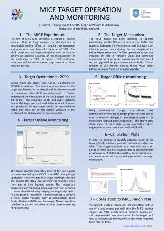
Background The decision to implement a firmware based BPS system was taken based upon discussions/recommendations from ISIS staff in August last year. The firmware based BPS system aims to monitor the trajectory of the target on an actuation by actuation basis by comparing key points in the trajectory to similar key points in a pre-computed reference trajectory. The comparison between the key values and the actual target trajectory is done in firmware to ensure that the system remains reliable even in the event of a disconnection between the computer and controller.
(cm) Begin Actuation End actuation Record actuation time Enter capture mode • Set Point 1 • Flip Acceleration • Record time • Set Point 2 • Position Set • Flip Acceleration Minimum Position Record position & time
(cm) Limits on “normal” Actuation, if outside send BPS error Begin Actuation End actuation Record actuation time Enter capture mode • Set Point 1 • Flip Acceleration • Record time • Set Point 2 • Position Set • Flip Acceleration Minimum Position Record position & time
FPGA Implementation • 8 USB registers set by control software • Provide upper and lower limits for: • FPGA Firmware monitors above position/times and throws an error if they lie outside the limits set in the registers. • The start position and final position are implicitly monitored by the target system. Any deviation from a normal range will throw an error, this has been tied into the BPS system. "USB_SP1_MAX_TIME" "USB_SP1_MIN_TIME" "USB_MIN_POS_MAX_TIME” "USB_MIN_POS_MIN_TIME” "USB_MIN_POS_MAX_VALUE” "USB_MIN_POS_MIN_VALUE” "USB_ACT_MAX_TIME“ "USB_ACT_MIN_TIME“ SP1 Time Actuation Time. Minimum Position Minimum Position Time
Calculation of Trajectory Target acceleration decays exponentially due to decaying power in capacitor bank: C function calculates trajectory from: a0, tRC, Starting Position, SP1 and SP2. Fit using C function to analogue data shown as red line => Limits can be calculated from the expected trajectory and downloaded to the FPGA registers (cm) a0 depends on current and can be calculated for different voltage or temperature coils. All necessary functions for calculating a0 and trajectory included in c++ class.
Example from Sheffield target SP1 time Coil Temperature Target warm up Coolant Temperature Minimum Position Minimum Position Time
Hardware We were asked to provide 2 independent sets of relay contacts for the BPS system itself: FPGA Relay DriverEach relay driver is connected to separate FPGA logic pin. RelayRated to 1A 30VDC but PCB tracks limited to about 250mA BPS Logic Required to switch 2 relays. 24VDC, 16.8mA total. 50R Driver Added a third logical output to give a monitoring signal connected to a BNC
Hardware Row of relays down the RHS of board DC2. There are 2 spare relays on the circuit board, so if more relays are required then this can be accommodated. Relay Contacts Available here 50R signal for sending to ISIS CR – If required Back panel connectors
Calibration & Testing Plans • Current calibration for outdated test system in Sheffield. • Single minimum position. • Limited data recorded before controller was moved to R78. • New calibration required for ISIS, R78 targets. • Multiple minimum positions. • Determination of upper/lower limits to place on actuation. • Thorough testing in R78 required to ensure system is working reliably prior to installation.
Conclusion • FPGA code and Electronics implemented, but requires testing. • Software for estimating parameters is also implemented. • Works well for Sheffield target. • Calibration required for R78 target. • upper/lower limits on actuation need setting. • Control software upgrade underway to include BPS functionality. • Thorough testing in R78 required to ensure system is working reliably prior to installation.