Download
1 / 14
150 likes | 300 Vues
CollUSM August 1 st 2014. Many thanks to…. BE. BEAM DEPARTMENT. E. Quaranta , F. Carra , P. Hermes. U pdates of irradiation tests at GSI on LHC collimator materials.

E N D
CollUSM August 1st 2014 Many thanks to… BE BEAM DEPARTMENT E. Quaranta, F. Carra, P. Hermes Updates of irradiation tests at GSI on LHC collimator materials M. Tomut, C. Hubert, K. Kupka, J. StadlmannGSI Helmholtzzentrum für Schwerionenforschung, Darmstadt, GermanyA. Bertarelli, F. Carra, P. Hermes, S. Redaelli, A. RossiCERN, Geneva, SwitzerlandOurmaterialssuppliers: M. Kitzmantel, E. NeubauerRHP-Technology GmbH, Seibersdorf, AustriaS. BizzaroBrevettiBizz
Outline Motivation and Objective GSI irradiation facility Feb-Mar 2014 irradiation campaign July 2014 irradiation campaign What’s next?
Motivation and Objective • Collimators subjected to high level of radiation doses during the normal LHC operation which lead to DRAMATIC CHANGES in the material properties: • Decrease in thermal conductivity • Increase in electrical resistivity • Increase in Young’s modulus • Deformation MINIMIZE the WORSENING of phys/mech properties due to radiation-induced effects Collimator materials MUST Will the present and the novel collimator material survive the HL-LHC scenario? The answerwill take into account their behaviour in highly irradiation environment. Elena Quaranta
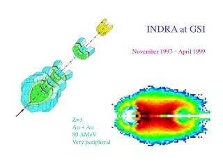
GSI facility SIS all ion speciesp, Ar, Au, Pb, U M-Branch Ion Sources X0 UNILAC 100 m Mikroprobe UNILAC beamlines Energy: 3.6-11.4 MeV/u Range: 40-120 µm beam spot area : 10x10 mm to 50x50 mm Cave A Elena Quaranta
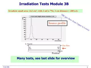
Feb-Mar 2014 irradiation campaign • 238U irradiation:1.14 GeV, 0.5 ms, 0.6 Hz, 4x10⁹ions/cm2s • 208Bi irradiation: 1 GeV, 0.5 ms, 3.4 Hz, 1.2x10⁹ions/cm2s • CuCD, CFC (2 orientations), MoGr(MG 3110P, 2 orientations, samples not annealed) irradiatedwithfuences up to 5e13 i/cm2 Elena Quaranta
July 2014 irradiation campaign • 197Au irradiation: • - ion energy: 945 MeV • - pulse frequency: 40 Hz • - flux: ~1-2x10⁹ions/cm2s • - beam spot: 2.2x2.2 cm • C irradiation (on-going): 11.4 MeV/u, flux: 5x10⁹ions/cm2s Elena Quaranta
Thermal properties degradation On-Line monitoring during irradiation with thermal camera (acquisition rate: 2kHz). Estimation of time constant at cooling on: • Mo-Gr: 2 orientations x 2 different annealing processes (1150°C and 1300°C for 4h) • CFC: 2 orientations • CuCD Another batch of samples is currently under C-ions irradiation at fluence up to 1e14 i/cm2 CuCD CFC MG 5220S fluences: 1e11, 1e12, 1e13, 5e13 Au-ions/cm2 at fluxes ~2e9 Au-ions/cm2s fluence up to 1e13 Au-ions/cm2 at fluxes ~1e9 Au-ions/cm2s Elena Quaranta
Radiation-induced deformation Measurement at optical microscope of shortening after irradiation on: • carbon fibers (3 mm, Ø= few µm, Granoc XN-100-03Z), used as MG composite reinforcement • Quite challenging • to mount on the holders!! carbon fibers fluences: 1e11, 1e12, 1e13, 5e13 Au-ions/cm2 at fluxes ~1e9 Au-ions/cm2s Elena Quaranta
What’s next? • Thermo-mechanical and structural characterization of irradiated samples • Quantitative evaluation of online thermal camera monitoring data • Further irradiation during next beam-time (preliminary schedule): Mid-August: • Low duty cycle Au-ionsirradiation Mid-September: -irradiation withXe-ionsand Au-ions October/November: - irradiation with laser Elena Quaranta
CFC AC-150K • Developed by Tatsuno(Japan) • Composition : • Graphite flakes • Carbon fibers • Density: 1.67 g/cm3 Currently used as TCPs and TCSGs active jaw material Main limitations: • Poor electrical conductivity (0.18 MS/m) • RF Impedance induced beam perturbations • Limited Radiation Hardness • Reduced Lifetime for LHC operations • Need for replacing degraded Collimators Elena Quaranta
Copper-Diamond composite • Developed by RHP-Technology (Austria) • Composition : • 60%v diamonds (90% 100µm, 10% 45 µm) • 39%v Cu powder (45 µm) • 1%v B powder (5 µm) • No diamond degradation • Thermal (~490 Wm-1K-1) and electrical conductivity (~12.6 MSm-1) • No direct interface between Cu and CD (lack of affinity). Partial bonding bridging assured by Boron Carbides limits mechanical strength (~120 MPa). • Cu low melting point (1083 °C) • CTE increases significantly with T due to high Cu content (from ~6 ppmK-1 at RT up to ~12 ppmK-1 at 900 °C) Limitation for collimator! BC “bridge” stuck on CD surface. No CD graphitization Elena Quaranta
MG: composition and production • Basic composition & main production parameters: • 40%v natural graphite flakes (Asbury) • 20%v short carbon fibers(300 µm, CytekDKD) • 20%v long carbon fibers(3 mm,Granoc XN-100-03Z), blended • 20%v Mo powder (5 µm) • Powders pre-cleaning under H2-N2 atmosphere at 600°C • RHP: complete melting of Mo2C at ~2600°C, 35 MPa applied pressure (in steps), reducing H2-N2 atmosphere at 10-4 mbar. Graphite and molybdenum powder MG 5220S plate Elena Quaranta