Download
1 / 41
410 likes | 432 Vues
Explore atomic-scale variations in nanostructures using the tight-binding approach for in-depth understanding of electronic transport phenomena. Investigate valley degeneracies, strain effects, and quantum computing states in novel materials.

E N D
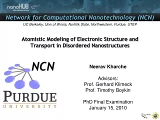
Atomistic Modeling of Electronic Structure and Transport in Disordered Nanostructures Neerav Kharche Advisors: Prof. Gerhard Klimeck Prof. Timothy Boykin PhD Final Examination January 15, 2010
Moore’s Law • From http://www.intel.com/technology/mooreslaw/index.htm
Nanoelectronic Device Scaling 2015-2019 Research • Channel doping • S/D doping • Strained channel • New gate dielectrics • Device geometries • Channel materials • High-k dielectrics Acknowledgement: Robert Chau, Intel III-V channel devices Emerging QC devices Low-power & powerful QC algorithms Low-power & high-speed 3
Atomic Scale Disorders in Nanoscale Devices SiGe Si Novel channel materials ~ 4 nm In InGaAs Ga InAs As D.H. Kim et. al., EDL 2008 Alloy disorder Quantum Computing devices Interface roughness Friesen et al., PRB, 2003 Goswami et al., Nature Physics, 2007 4
Tight-Binding Approach (1) • Bandstructure and effective mass • Carrier confinement • Atomic scale material variations • Local strain variations • Atomistic treatment of electric and magnetic fields InGaAs InAs InGaAs
Tight-Binding Approach (2) • Valley-splitting • Highly dependent on atomic scale thickness variations • Need atomistic modeling technique such as tight-binding SiGe/SiO2 Si (001) SiGe/SiO2 Single valley Two valleys 2nd Si L Boykin et al., APL. 2004
Outline • Motivation • Tight-Binding Approach to Model Atomic Scale Variations • Summary of Results • Valley Degeneracies in (111) Si Quantum Wells • Valley-Splitting in (100) SiGe/Si/SiGe Quantum Wells • Transport Characteristics of AlGaAs Nanowires • Ultra-Scaled InAs HEMTs • Performance Analysis of Ultra-Scaled InAs HEMTs • Modeling Approach • Comparison to Experiments • Scaling Considerations • Summary of Contributions • Outlook
Outline • Motivation • Tight-Binding Approach to Model Atomic Scale Variations • Summary of Results • Valley Degeneracies in (111) Si Quantum Wells • Valley-Splitting in (100) SiGe/Si/SiGe Quantum Wells • Transport Characteristics of AlGaAs Nanowires • Ultra-Scaled InAs HEMTs • Performance Analysis of Ultra-Scaled InAs HEMTs • Modeling Approach • Comparison to Experiments • Scaling Considerations • Summary of Contributions • Outlook
Valley Degeneracies in (111) Si Quantum Wells Objective Resolve discrepancies in experimentally observed and theoretically predicted valley degeneracies Effect of surface miscut on the electronic structure Approach Supercell tight-binding approach to model surface miscuts Effective mass based valley-projection model to determine the directions of valley-minima of large supercells Insight Atomistic basis representation is essential to capture the effect of mono-atomic steps resulting from miscut Results Flat (111) Si QW shows 6 fold valley degeneracy Miscut causes 2-4 splitting due to different effective masses in confinement direction Theory: 6 fold Expt: 2 & 4 fold Expt: Eng et al., PRL., 2007 Theory: Kharche et al., APL. 2009
Outline • Motivation • Tight-Binding Approach to Model Atomic Scale Variations • Summary of Results • Valley Degeneracies in (111) Si Quantum Wells • Valley-Splitting in (100) SiGe/Si/SiGe Quantum Wells • Transport Characteristics of AlGaAs Nanowires • Ultra-Scaled InAs HEMTs • Performance Analysis of Ultra-Scaled InAs HEMTs • Modeling Approach • Comparison to Experiments • Scaling Considerations • Summary of Contributions • Outlook
Valley-Splitting in (100) SiGe/Si/SiGe Quantum Wells Strain – 10 million atoms SiGe Alloy disorder Elect. – 2 million atoms Si Valley splitting E3 Δs Valley + spin splitting E2 Valley splitting Valley + spin splitting Δv Δs E1 Rough steps Δs QC states Δv E0 15 nm Δs QC states 10 nm SiGe Si 16 nm SiGe 150 nm • Objective: • Model experimentally observed valley splitting in strained (100) SiGe/Si/SiGe quantum wells • Resolve discrepancies in experiment and theory • Approach: • Model large structure • 150nm x 16nm x 15nm • 10 million atoms • No changes to the published tight binding parameters • Result: • Match experiment well • Atomic disorder critical in the device understanding • Quantitative model of complex system SiGe Si (001) SiGe Expt: Goswami, Nature Physics, 2007 Theory: Kharche et al., APL., 2007
Outline • Motivation • Tight-Binding Approach to Model Atomic Scale Variations • Summary of Results • Valley Degeneracies in (111) Si Quantum Wells • Valley-Splitting in (100) SiGe/Si/SiGe Quantum Wells • Transport Characteristics of InAlAs Nanowires • Ultra-Scaled InAs HEMTs • Performance Analysis of Ultra-Scaled InAs HEMTs • Modeling Approach • Comparison to Experiments • Scaling Considerations • Summary of Contributions • Outlook
Objective Method to model bandstructure of disordered nanowires Detailed understanding of transport by comparing bandstructure and transmission characteristics Approach Transmission: Non-equilibrium Green’s function method Bandstructure: Supercell calculation and zone-unfolding Results Transmission: noisy and reduced due to disorder Unfolded bands relate well to transmission Peaks in transmission due to localization Impact m* and Eg extracted from unfolded bands can be used in simple models such as top-of-the-barrier or effective mass device simulators 3 z [nm] 2 1 1 20 15 2 y [nm] 10 3 x [nm] 5 Al Ga As Energy [eV] Energy [eV] Transmission kx [π/a] Electronic Structure and Transmission Characteristics of Disordered AlGaAs Nanowires Energy [eV] Slab Transmission Energy [eV] Energy [eV] AlGaAs – Boykin et al., IEEE TNANO 2007, SiGe – Kharche et al., JCE 2007 Transmission kx [π/a]
Outline • Motivation • Tight-Binding Approach to Model Atomic Scale Variations • Summary of Results • Valley Degeneracies in (111) Si Quantum Wells • Valley-Splitting in (100) SiGe/Si/SiGe Quantum Wells • Transport Characteristics of InAlAs Nanowires • Ultra-Scaled InAs HEMTs • Performance Analysis of Ultra-Scaled InAs HEMTs • Modeling Approach • Comparison to Experiments • Scaling Considerations • Summary of Contributions • Outlook
Performance Analysis of Ultra-Scaled InAs FETs Objective Develop: a methodology to simulate ultra-scaled InAs FETs Benchmark: match experimental I-Vs for “large” devices Lg = 30 - 50nm Improve: device design for scaling down to 20nm node Results/Impact Good quantitative match to experiments Performance optimization of 20nm device Gate Lg=20nm Lg Source Drain n+ Cap n+ Cap InP etch stop δ-doped layer InAlAs InGaAs InAs InGaAs InAlAs InP Substrate Sim. vs. Expt. Performance optimization Vd=0.50 V Vd=0.05 V D.H. Kim, EDL 2008 Kharche et al., IEDM 2009
Outline • Motivation • Tight-Binding Approach to Model Atomic Scale Variations • Summary of Results • Valley Degeneracies in (111) Si Quantum Wells • Valley-Splitting in (100) SiGe/Si/SiGe Quantum Wells • Transport Characteristics of InAlAs Nanowires • Ultra-Scaled InAs HEMTs • Performance Analysis of Ultra-Scaled InAs HEMTs • Modeling Approach • Comparison to Experiments • Scaling Considerations • Summary of Contributions • Outlook
Motivation: Why III-V HEMTs? • III-V: Extraordinary electron transport properties and high injection velocities • HEMTs: Very similar structure to MOSFETs except high-κ dielectric layer • Excellent to Test Performancesof III-V material without interface defects • Every Year Devices with a Shorter Gate Length Introduced by del Alamo’s Group at MIT • Excellent to Test Simulation Models • Develop simulation tools and benchmark with experiments • Predict performance of ultra-scaled devices 2007: 40nm 2008: 30nm D.H. Kim et al., EDL 29, 830 (2008)
Outline • Motivation • Tight-Binding Approach to Model Atomic Scale Variations • Summary of Results • Valley Degeneracies in (111) Si Quantum Wells • Valley-Splitting in (100) SiGe/Si/SiGe Quantum Wells • Transport Characteristics of InAlAs Nanowires • Ultra-Scaled InAs HEMTs • Performance Analysis of Ultra-Scaled InAs HEMTs • Modeling Approach • Comparison to Experiments • Scaling Considerations • Summary of Contributions • Outlook
Gate Drain Source Simulation Domain: Intrinsic device Device Geometry and Simulation Domain • Intrinsic device • Near gate contact • Self consistent 2D Schrodinger-Poisson • Electrons injected from all contacts • Extrinsic source/drain contacts • Series resistances RS and RD Extrinsic device Lg Source Drain n+ Cap n+ Cap InP etch stop δ-doped layer InAlAs M. Luisier et al., IEEE Transactions on Electron Devices, vol. 55, p. 1494, (2008). InAs InGaAs InP Substrate R. Venugopal et al., Journal of Applied Physics, vol. 95, p. 292, (2004).
Outline • Motivation • Tight-Binding Approach to Model Atomic Scale Variations • Summary of Results • Valley Degeneracies in (111) Si Quantum Wells • Valley-Splitting in (100) SiGe/Si/SiGe Quantum Wells • Transport Characteristics of InAlAs Nanowires • Ultra-Scaled InAs HEMTs • Performance Analysis of Ultra-Scaled InAs HEMTs • Modeling Approach • Comparison to Experiments • Scaling Considerations • Summary of Contributions • Outlook
Transfer Characteristics: Id-Vgs Material Parameters
Output Characteristics: Id-Vds • Conclusion: • Good agreement for all Lg’s • Less ballistic at Lg=50nm • Use models and material parameters to design ultra-scaled devices (Lg=20nm)
Outline • Motivation • Tight-Binding Approach to Model Atomic Scale Variations • Summary of Results • Valley Degeneracies in (111) Si Quantum Wells • Valley-Splitting in (100) SiGe/Si/SiGe Quantum Wells • Transport Characteristics of InAlAs Nanowires • Ultra-Scaled InAs HEMTs • Performance Analysis of Ultra-Scaled InAs HEMTs • Modeling Approach • Comparison to Experiments • Scaling Considerations • Summary of Contributions • Outlook
What can be changed? • Gate geometry • Channel thickness: tInAs • Insulator thickness: tins • Metal work function engineering: ΦM Better control of surface potential Gate leakage reduction and E-mode operation Lg=20nm Gate ΦM In0.52Al0.48As tins Drain In0.53Ga0.47As Source tInAs InAs
Parameters and Performances Summary (1) Gate geometry (2) Channel thickness (3) Insulator thickness (4) Metal work function • Improved gate control • Lower SS • higher ION/IOFF • Higher gate leakage • Higher SS • Lower ION/IOFF • Gate leakage reduction • Lower SS • Higher ION/IOFF SS ION/IOFF 1 Lg=20nm 3 4 4 2 2 1 3
HEMT Simulator on nanoHUB.org • OMEN_FET: • HEMTs, Single- and Double-Gate devices • Electron transport in Si and III-V • Current Flow Visualization http://nanoHUB.org/tools/omenhfet Run your own simulations!
Outline • Motivation • Tight-Binding Approach to Model Atomic Scale Variations • Summary of Results • Valley Degeneracies in (111) Si Quantum Wells • Valley-Splitting in (100) SiGe/Si/SiGe Quantum Wells • Transport Characteristics of InAlAs Nanowires • Ultra-Scaled InAs HEMTs • Performance Analysis of Ultra-Scaled InAs HEMTs • Modeling Approach • Comparison to Experiments • Scaling Considerations • Summary of Contributions • Outlook
SiGe Si Summary of Contributions (1) • (111) Si quantum wells: Explained 2-4 valley degeneracy breaking (APL 2009) • Miscut (100) SiGe/Si/SiGe quantum wells: Provided qualitative and quantitative understanding of valley splitting (APL 2007) Cause: Surface miscut Expected Observed Alloy disorder SiGe Si Rough steps No disorder SiGe
Simulation Domain: Intrinsic device Lg=20nm Summary of Contributions (2) • AlGaAs and SiGe nanowires: Provided understanding of transmission coefficients by employing zone-unfolding method (TNANO 2007, JCE 07) • InAs HEMTs: Demonstrated quantitative agreement between experiments and simulations. Performance optimizations for ultra-scaled HEMTs (IEDM 09) Energy [eV] Energy [eV] Transmission kx [π/a] Sim. vs. Expt. Performance optimization Extrinsic device Vd=0.50 V Vd=0.05 V
Outline • Motivation • Tight-Binding Approach to Model Atomic Scale Variations • Summary of Results • Valley Degeneracies in (111) Si Quantum Wells • Valley-Splitting in (100) SiGe/Si/SiGe Quantum Wells • Transport Characteristics of InAlAs Nanowires • Ultra-Scaled InAs HEMTs • Performance Analysis of Ultra-Scaled InAs HEMTs • Modeling Approach • Comparison to Experiments • Scaling Considerations • Summary of Contributions • Outlook
Outlook (1) • Valley degeneracies in (110) Si QWs • Both 4 and 2 fold valley degeneracies are reported in experiments • Flat (110) => 2 fold degenerate • Miscut (110) => 4 fold degenerate • Effect of Ge concentration on valley splitting in (100) SiGe/Si/SiGe QWs • Disorder in SiGe reduces valley splitting and sensitivity to Ge concentration SiGe barrier Si QW VCA SiGe Random alloy SiGe 2.17 nm 25.53 nm ΔEC U [eV] z [nm]
Gate Outlook (2) • Supercell approach and zone-unfolding • Electronic structure of rough nanowires and QWs • Hole transport in SiGe pMOS devices • III-V MOSFETs Schottky gate MOS gate Source Drain n+ Cap n+ Cap InP etch stop InAlAs δ-doping InAs InGaAs InAlAs Intel, IEDM 2009
Acknowledgements Advisors: • Professor Gerhard Klimeck • Professor Timothy Boykin Committee members: • Professor Mark Lundstrom • Professor Supriyo Datta • Professor Ronald Reifenberger Dr. Mathieu Luisier Klimeck Group Members and Labmates
Gate Geometry and Gate Leakage Current 1 (a) 3 2 (b) 1)Include Series Resistances 2) Include Gate Leakage Current 3) Include the Proper Gate Geometry Flat (a) or Curved (b) Gate leakage reduced in curved gate device
InAs and InAlAs Layer Thickness gate leakage IOFF increases • InAs Channel Scaling: • Better electrostatic control • lower SS • larger ION/IOFF ratio • Increase of transport m* • reduced vinj, higher Ninv => higher ION • Increase of gate leakage current • ION/IOFF ratio saturates • InAlAs Insulator Scaling: • Better electrostatic control (due to larger Cox) • Increase of gate leakage current • larger IOFF • larger SS • smaller ION/IOFF ratio
InAs (Channel) Layer Thickness • InAs Channel Scaling: • Better electrostatic control • lower SS • larger ION/IOFF ratio • Increase of transport m* • reduced vinj, higher Ninv => higher ION • Increase of gate leakage current • ION/IOFF ratio saturates IOFF increases Gate Source In0.53Ga0.47As Drain tInAs InAs In0.52Al0.48As
InAlAs (Insulator) Layer Thickness • InAlAs Insulator Scaling: • Better electrostatic control (due to larger Cox) • Increase of gate leakage current • larger IOFF • larger SS • smaller ION/IOFF ratio gate leakage Gate tins Source In0.53Ga0.47As Drain InAs In0.52Al0.48As
Work Function Engineering • Work Function Increase: • Shift towards enhancement mode • Decrease of gate leakage current • Allows for thinner insulator layer • steeper SS • larger ION/IOFF ratio
Gate Leakage Mechanism • Electrons tunnel from gate into InAs channel • Tunneling barriers • InAlAs and InGaAs • Position dependent barriers • Current crowding at edges (due to lower tunneling barriers) • Barriers modulated by ΦM ΦM
Work Function Engineering (2) • Characteristics: • Same Gate Overdrive • same thermionic current (source to drain) • Gate Fermi levels shifted by ΔΦM • different tunneling barrier height • ΦM =4.7 eV • tunnel through InAlAs only • larger Ig • ΦM =5.1 eV • tunnel through InAlAs and InGaAs • lower Ig ΦM =5.1 eV ΦM =4.7 eV