Download
1 / 16
160 likes | 183 Vues
Dive into the world of sequential circuits with a detailed overview of flip-flops and latches. Learn how these components store data based on trigger edges and control inputs, and explore different types of flip-flops and their functions. Understand clocking events, edge triggers, and the applications of flip-flops in computer memory and computational circuits.

E N D
Overview • Latches respond to trigger levels on control inputs • Example: If G = 1, input reflected at output • Difficult to precisely time when to store data with latches • Flip flips store data on a rising or falling trigger edge. • Example: control input transitions from 0 -> 1, data input appears at output • Data remains stable in the flip flop until until next rising edge. • Different types of flip flops serve different functions • Flip flops can be defined with characteristic functions.
D D Latch S S’ Q C Q’ R’ R S R C Q Q’ D C Q Q’ 0 0 1 Q0 Q0’ Store 0 1 1 0 1 Reset 1 0 1 1 0 Set 1 1 1 1 1 Disallowed X X 0 Q0 Q0’ Store 0 1 0 1 1 1 1 0 X 0 Q0 Q0’ • When C is high, D passes from input to output (Q)
Positive edge triggered D Q C Q’ Hi-Lo edge Lo-Hi edge D C Q Q’ 0 0 1 1 1 0 X 0 Q0 Q0’ Clocking Event • What if the output only changed on a C transition?
Master-Slave D Flip Flop • Consider two latches combined together • Only one C value active at a time • Output changes on falling edge of the clock
Positive edge triggered D Q C Q’ D C Q Q’ 0 0 1 1 1 0 X 0 Q0 Q0’ D Flip-Flop • Stores a value on the positive edge of C • Input changes at other times have no effect on output D gets latched to Q on the rising edge of the clock.
Clocked D Flip-Flop • Stores a value on the positive edge of C • Input changes at other times have no effect on output
Hi-Lo edge Lo-Hi edge Positive and Negative Edge D Flip-Flop • D flops can be triggered on positive or negative edge • Bubble before Clock (C) input indicates negative edge trigger
Positive Edge-Triggered J-K Flip-Flop J K CLK Q Q’ • Created from D flop • J sets • K resets • J=K=1 -> invert output 0 0 Q0 Q0’ 0 1 0 1 1 0 1 0 1 1 TOGGLE
Clocked J-K Flip Flop • Two data inputs, J and K • J -> set, K -> reset, if J=K=1 then toggle output Characteristic Table
T Q Q’ C 0 Q0 Q0’ 1 TOGGLE Positive Edge-Triggered T Flip-Flop • Created from D flop • T=0 -> keep current • K resets • T=1 -> invert current
Asynchronous Inputs • J, K are synchronous inputs • Effects on the output are synchronized with the CLK input. • Asynchronous inputs operate independently of the synchronous inputs and clock • Set the FF to 1/0 states at any time.
Asynchronous Inputs • Note reset signal (R) for D flip flop • If R = 0, the output Q is cleared • This event can occur at any time, regardless of the value of the CLK
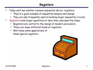
Parallel Data Transfer • Flip flops store outputs from combinational logic • Multiple flops can store a collection of data
Summary • Flip flops are powerful storage elements • They can be constructed from gates and latches! • D flip flop is simplest and most widely used • Asynchronous inputs allow for clearing and presetting the flip flop output • Multiple flops allow for data storage • The basis of computer memory! • Combine storage and logic to make a computation circuit • Next time: Analyzing sequential circuits.