
New Chip Design
E N D
Presentation Transcript
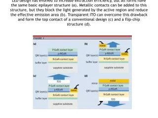
LED design has evolved to increase extraction efficiency, but all forms have the same basic epilayer structure (a). Metallic contacts can be added to this structure, but they block the light generated by the active region and reduce the effective emission area (b). Transparent ITO can overcome this drawback and form the top contact of a conventional design (c) and a flip-chip structure (d).
Illustrations Figure 1. Philips Lumileds has developed a thin-film flip-chip (TFFC) LED (a) that offers better performance than the flip-chip structures (b) currently employed in its Luxeon products. The TFFC LED also offers a higher light output and greater efficacies than vertical thin-film chips (c).
Figure 2. LED arrays based on vertically injected thin-film (VTF) LEDs require a wire bond for each device (a). These wires block some of the emitted light and force the primary optic that is used in projection displays and illumination systems away from the emitting surface of the LED. Greater light coupling efficiencies are produced with Philips Lumileds' VTTF design (b), which eliminates the loss in light output caused by wires and reduces the distance to the primary optic.
Figure 3. A split-wafer study of blue LEDs reveals that the TFFC design delivers a higher light output than VTF and FC equivalents at all drive currents up to 1A. To ease comparison, light output has been normalized to that of an FC-LED at 1A. The VTF-LED used in this test has a conventional design, with a reflective p-contact evaporated onto the p-doped side of the device and a GaAs intermediate substrate. Deposited aluminum forms the mesh-like n-contact and the wire-bond pads, and typically 50% of the top surface emits light. To minimize light occlusion effects, the resistivity of regions beneath the mesh contact has been increased with hydrogen-ion implantation.
Figure 4. The encapsulated 425nm blue TFFC LED can deliver a light output of almost 2W at 2A. The test was carried out under direct current conditions, with heatsinks used to maintain an operating temperature of 25°C.
Figure 5. Coating the blue TFFC chip with a YAG:Ce phosphor produces a white-light device with a maximum efficacy of almost 150lm/W.
Philips Lumileds Launches New Luxeon K2 with TFFC, the Industry’s First 1A LED