Transport Layer
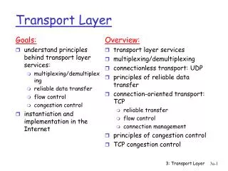
Transport Layer. Michalis Faloutsos Many slides from Kurose-Ross. Transport Layer Functionality. Hide network from application layer Transport layer resides at end points Sees the network as a black box. Transport Layers of the Internet. TCP: reliable protocol


Transport Layer
E N D
Presentation Transcript
Transport Layer Michalis Faloutsos Many slides from Kurose-Ross
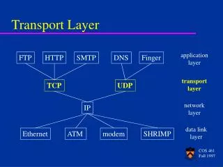
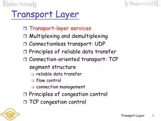
Transport Layer Functionality • Hide network from application layer • Transport layer resides at end points • Sees the network as a black box
Transport Layers of the Internet • TCP: reliable protocol • Guarantees end-to-end delivery • Self-controls rate: congestion and flow control • Connection oriented: handshake, state • Ordered delivery of packets to application • UDP: unreliable protocol • Non-regulated sending rate • Multiplexing-demultiplexing
full duplex data: bi-directional data flow in same connection MSS: maximum segment size connection-oriented: handshaking (exchange of control msgs) init’s sender, receiver state before data exchange flow controlled: sender will not overwhelm receiver point-to-point: one sender, one receiver reliable, in-order byte steam: no “message boundaries” pipelined: TCP congestion and flow control set window size send & receive buffers TCP: What and How For more: RFCs: 793, 1122, 1323, 2018, 2581
32 bits source port # dest port # sequence number acknowledgement number head len not used rcvr window size U A P R S F checksum ptr urgent data Options (variable length) application data (variable length) TCP segment structure URG: urgent data (generally not used) counting by bytes of data (not segments!) ACK: ACK # valid PSH: push data now (generally not used) # bytes rcvr willing to accept RST, SYN, FIN: connection estab (setup, teardown commands) Internet checksum (as in UDP)
TCP overview • TCP is a sliding window protocol • Sender can have (Window) bytes in flight • Operates with cumulative ACKs • It includes control for the sending rate • Flow control: receiver-set sending rate • Congestion control: network-aware sending rate Congwin
Seq. #’s: byte stream “number” of first byte in segment’s data ACKs: seq # of next byte expected from other side cumulative ACK Q: how receiver handles out-of-order segments A: TCP spec doesn’t say, - up to implementor time TCP seq. #’s and ACKs Host B Host A User types ‘C’ Seq=42, ACK=79, data = ‘C’ host ACKs receipt of ‘C’, echoes back ‘C’ Seq=79, ACK=43, data = ‘C’ host ACKs receipt of echoed ‘C’ Seq=43, ACK=80 simple telnet scenario
TCP in a nutshell I. Slow start phase (actually this is fast increase) • Start with a window of 1 (or 2) • Successful ACK: Increase window by one 1 max size segment • Do this up to a threshold: sshthresh II. Congestion control phase • Increase window by 1 max size segment every RTT • Drop window in half, if there is congestion • Packet loss: duplicate ACKs • Time expiration
end-end control (no network assistance) transmission rate limited by congestion window size, Congwin, over segments: w * MSS throughput = Bytes/sec RTT TCP Congestion Control Congwin w segments, each with MSS bytes sent in one RTT:
TCP is “probing” for usable bandwidth: ideally: transmit as fast as possible (Congwin as large as possible) without loss increaseCongwin until loss (congestion) loss: decreaseCongwin, then begin probing (increasing) again TCP congestion control: Intuition
TCP has two “phases” slow start: start from small, increase quickly congestion avoidance: Additive Increase Multiplicative Decrease important variables: Congwin threshold: defines threshold between two slow start phase, congestion control phase TCP congestion control:
exponential increase (per RTT) in window size loss event: timeout (Tahoe TCP) and/or or three duplicate ACKs (Reno TCP) Slowstart algorithm time TCP Slowstart Host A Host B one segment RTT initialize: Congwin = 1 for (each segment ACKed) Congwin++ until (loss event OR CongWin > threshold) two segments four segments
Why Call it Slow Start ? • The original version of TCP suggested that the sender transmit as much as the Advertised Window permitted. • Routers may not be able to cope with this “burst” of transmissions. • Slow start is slower than the above version -- ensures that a transmission burst does not happen at once.
TCP Congestion Avoidance Congestion avoidance /* slowstart is over */ /* Congwin > threshold */ Until (loss event) { every w segments ACKed: Congwin++ } threshold = Congwin/2 Congwin = 1 perform slowstart 1 1: TCP Reno skips slowstart (fast recovery) after three duplicate ACKs
Remember: bytes vs packets! CW += MSS * MSS/CW Thres = Max( 2* MSS, InFlightData/2) MSS: max segment size InFlighData: un-ACK-ed data RFC 2581: TCP Congestion Control TCP Congestion: Real Life is Hairy! Congestion avoidance /* slowstart is over */ /* Congwin > threshold */ Until (loss event) { every w segments ACKed: Congwin++ } threshold = Congwin/2 Congwin = 1 perform slowstart 1
Fairness goal: if N TCP sessions share same bottleneck link, each should get 1/N of link capacity TCP congestion avoidance: AIMD:additive increase, multiplicative decrease increase window by 1 per RTT decrease “window” by factor of 2 on loss event TCP Fairness and AIMD TCP connection 1 bottleneck router capacity R TCP connection 2
Two competing sessions: Additive increase gives slope of 1, as throughout increases multiplicative decrease decreases throughput proportionally Why is TCP fair? equal bandwidth share R loss: decrease window by factor of 2 congestion avoidance: additive increase Connection 2 throughput loss: decrease window by factor of 2 congestion avoidance: additive increase Connection 1 throughput R
Macroscopic Description of Throughput • Assume window toggling: W/2 to W • High rate: W * MSS / RTT • Low rate: W * MSS / 2 RTT • Rate increase is linearly between two extremes • Average throughput: • 0.75 * W * MSS / RTT
TCP: reliable data transfer event: data received from application above Simplified sender, assuming create, send segment • one way data transfer • no flow, congestion control wait for event event: timer timeout for segment with seq # y wait for event retransmit segment event: ACK received, with ACK # y ACK processing
TCP sender 00sendbase = initial_sequence number 01 nextseqnum = initial_sequence number 02 03 loop (forever) { 04 switch(event) 05 event: data received from application above 06 create TCP segment with sequence number nextseqnum 07 start timer for segment nextseqnum 08 pass segment to IP 09 nextseqnum = nextseqnum + length(data) 10 event: timer timeout for segment with sequence number y 11 retransmit segment with sequence number y 12 compute new timeout interval for segment y 13 restart timer for sequence number y 14 event: ACK received, with ACK field value of y 15 if (y > sendbase) { /* cumulative ACK of all data up to y */ 16 cancel all timers for segments with sequence numbers < y 17 sendbase = y 18 } 19 else { /* a duplicate ACK for already ACKed segment */ 20 increment number of duplicate ACKs received for y 21 if (number of duplicate ACKS received for y == 3) { 22 /* TCP fast retransmit */ 23 resend segment with sequence number y 24 restart timer for segment y 25 } 26 } /* end of loop forever */ Simplified TCP sender
TCP Receiver: ACK generation[RFC 1122, RFC 2581] TCP Receiver action delayed ACK. Wait up to 500ms for next segment. If no next segment, send ACK immediately send single cumulative ACK send duplicate ACK, indicating seq. # of next expected byte immediate ACK if segment starts at lower end of gap Event in-order segment arrival, no gaps, everything else already ACKed in-order segment arrival, no gaps, one delayed ACK pending out-of-order segment arrival higher-than-expect seq. # gap detected arrival of segment that partially or completely fills gap
Host A Host B Seq=92, 8 bytes data ACK=100 timeout X loss Seq=92, 8 bytes data ACK=100 time time lost ACK scenario TCP: retransmission scenarios Host A Host B Seq=92, 8 bytes data Seq=100, 20 bytes data Seq=92 timeout ACK=100 ACK=120 Seq=100 timeout Seq=92, 8 bytes data ACK=120 premature timeout, cumulative ACKs
Q: how to set TCP timeout value? longer than RTT note: RTT will vary too short: premature timeout unnecessary retransmissions too long: slow reaction to segment loss Q: how to estimate RTT? SampleRTT: measured time from segment transmission until ACK receipt ignore retransmissions, cumulatively ACKed segments SampleRTT will vary, want estimated RTT “smoother” use several recent measurements, not just current SampleRTT TCP Round Trip Time and Timeout
Setting the timeout EstimtedRTT plus “safety margin” large variation in EstimatedRTT -> larger safety margin TCP Round Trip Time and Timeout EstimatedRTT = (1-x)*EstimatedRTT + x*SampleRTT Exponential weighted moving average influence of given sample decreases exponentially fast typical value of x: 0.1 Timeout = EstimatedRTT + 4*Deviation Deviation = (1-x)*Deviation + x*|SampleRTT-EstimatedRTT|
Recall:TCP sender, receiver establish “connection” before exchanging data segments initialize TCP variables: seq. #s buffers, flow control info (e.g. RcvWindow) client: connection initiator Socket clientSocket = new Socket("hostname","port number"); server: contacted by client Socket connectionSocket = welcomeSocket.accept(); Three way handshake: Step 1:client end system sends TCP SYN control segment to server specifies initial seq # Step 2:server end system receives SYN, replies with SYNACK control segment ACKs received SYN allocates buffers specifies server-> receiver initial seq. # Step 3: Client replies with an ACK (using servers seq number) TCP Connection Management
Closing a connection: client closes socket:clientSocket.close(); Step 1:client end system sends TCP FIN control segment to server Step 2:server receives FIN, replies with ACK. Closes connection, sends FIN. Last ACK is never ACK-ed!! client server close FIN ACK close FIN ACK timed wait closed TCP Connection Management (cont.)
Step 3:client receives FIN, replies with ACK. Enters “timed wait” - will respond with ACK to received FINs Step 4:server, receives ACK. Connection closed. Sends FIN. Last ACK is never ACK-ed TCP Connection Management (cont.) client server closing FIN ACK closing FIN ACK timed wait closed closed
Congestion: informally: “too many sources sending too much data too fast for network to handle” different from flow control! manifestations: lost packets (buffer overflow at routers) long delays (queueing in router buffers) Major research issue Principles of Congestion Control
Consequences of Congestion • Large delays: throughput vs delay trade-off • We don’t want to operate near capacity • Finite buffers: lost packets • Resending of packets causes • More packets for the same goodput • Wasted bandwidth of the packet that gets dropped
two senders, two receivers one router, infinite buffers no retransmission large delays when congested maximum achievable throughput Causes/costs of congestion: scenario 1
one router, finite buffers sender retransmission of lost packet Causes/costs of congestion: scenario 2
Always: (goodput) If packets are dropped: l’ l = > l l in in out out Causes/costs of congestion: scenario 2
Four senders, multihop paths, timeout/retransmit Congestion in one link -> retransmits -> congestion in other links Causes/costs of congestion: scenario 3
Causes/costs of congestion: scenario 3 Another “cost” of congestion: when packet dropped, any “upstream transmission capacity used for that packet was wasted!
End-end congestion control: no explicit feedback from network congestion inferred from end-system observed loss, delay approach taken by TCP Network-assisted congestion control: routers provide feedback to end systems single bit indicating congestion (SNA, DECbit, TCP/IP ECN, ATM) explicit rate sender should send at Approaches towards congestion control Two broad approaches towards congestion control:
Current TCP Versions • TCP specs can be implemented in different ways • TCP versions: • Tahoe (basic as described) • Reno • Las Vegas
TCP Reno • Most popular TCP implementation • Fast retransmit on 3 duplicate ACKs • Fast recovery: cancel slow start after fast retransmission • Half the congestion window threshold, but start with congestion window equal to threshold • Go to congestion avoidance phase • Optimistic Rationale: • I hope there was only one packet lost • Since I sent it, I hope it arrives this time
TCP Vegas • Idea: infer problems from RTT delay • Reduce rate before you have loss • What is a “sign” of congestion: • When RTT increases above a threshold • Sending rate flattens • Decrease sending rate linearly • Issues: • Estimate RTT • Set appropriate threshold
1100 900 700 Sending KBps 500 300 100 0.5 1.0 1.5 2.0 2.5 3.0 3.5 4.0 4.5 5.0 5.5 6.0 6.5 7.0 7.5 8.0 8.5 10 Queue size in router 5 0.5 1.0 1.5 4.0 4.5 6.5 8.0 Time (seconds) Intuition 70 60 50 40 KB 30 20 10 0.5 1.0 1.5 2.0 2.5 3.0 3.5 4.0 4.5 5.0 5.5 6.0 6.5 7.0 7.5 8.0 8.5 Time (seconds) Congestion Window Time (seconds) Average send rate at source 2.0 2.5 3.0 3.5 5.0 5.5 6.0 7.0 7.5 8.5 Driving on Ice Average Q length in router
TCP Vegas Details • Value of throughput with no congestion is compared to current throughput • If current difference is small, increase window size linearly • If current difference is large, decrease window size linearly • The change in the Slow Start Mechanism consists of doubling the window every other RTT, rather than every RTT and of using a boundary in the difference between throughputs to exit the Slow Start phase, rather than a window size value.
The TCP Vegas: Algorithm • Let BaseRTT be the minimum of all measured RTTs (commonly the RTT of the first packet) • If not overflowing the connection, then • ExpectedRate = CongestionWindow / BaseRTT • Source calculates current sending rate (ActualRate) once per RTT • Source compares ActualRate with ExpectedRate • Diff = ExpectedRate – ActualRate • if Diff < • -->increase CongestionWindow linearly • else if Diff > • -->decrease CongestionWindow linearly • else • -->leave CongestionWindow unchanged
Vegas Parameters • Parameters • : 1 packet • : 3 packets • Even faster retransmit • keep fine-grained timestamps for each packet • check for timeout on first duplicate ACK
Router Assisted Congestion Control • Random Early Detection • Explicit Congestion Notification Note: often this is referred to as Active Networking: ie routers are involved in perfomance. Active Nets is a much more general idea
RED: Random Early Detection • Idea: routers start dropping packets before they are congested • Benefits: make behavior smoother • How: • When queue is above a thres-1: drop packets with probability p • Issues: • setting the parameters • Estimating the queue size
Thresholds • two queue length thresholds • if AvgLen MinThreshold then • enqueue the packet • if MinThreshold < AvgLen < MaxThreshold • calculate probability P • drop arriving packet with probability P • if MaxThreshold AvgLen • drop arriving packet
RED: probability P • Not fixed • Function of AvgLen and how long since last drop (count) keeps track of new packets that have been queued while AvgLen has been between the two thresholds • TempP = MaxP * (AvgLen - MinThreshold) /(MaxThreshold - MinThreshold) • P = TempP/(1 - count * TempP) • MaxP is often set to 0.02, meaning that the gateway drops 1 out of 50 packets when queue size is halfway between MinThreshold and MaxThreshold
Comments on RED • Probability of dropping a particular flow's packet(s) is roughly proportional to the share of the bandwidth that flow is currently getting • MaxP is typically set to 0.02, meaning that when the average queue size is halfway between the two thresholds, the gateway drops roughly one out of 50 packets.
RED: Dropping probability P(drop) 1.0 MaxP A vgLen MinThresh MaxThresh
Selecting Parameters • if traffic is bursty, then MinThreshold should be sufficiently large to allow link utilization to be maintained at an acceptably high level • The difference between two thresholds should be larger than the typical increase in the calculated average queue length in one RTT; setting MaxThreshold to twice MinThreshold is reasonable for traffic on today's Internet