V Th
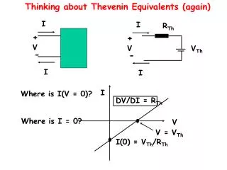
I. I. R Th. +. +. V. V. V Th. -. -. I. I. I. DV/DI = R Th. V. V = V Th. Thinking about Thevenin Equivalents (again). Where is I(V = 0)?. Where is I = 0?. I(0) = V Th /R Th. I C. V B. V C. I B. V E. I E. R E. The Emitter Follower. How are voltages ordered?.

V Th
E N D
Presentation Transcript
I I RTh + + V V VTh - - I I I DV/DI = RTh V V = VTh Thinking about Thevenin Equivalents (again) Where is I(V = 0)? Where is I = 0? I(0) = VTh/RTh
IC VB VC IB VE IE RE The Emitter Follower How are voltages ordered? How is VE related to VB? VCC VE=VB-0.6V What is the minimum VE ? VCC>VB>VE VE(min) = 0V What is VE if VB<0.6V? VE = 0V V0 = VE = VB-0.6V dV0 = dVB The output follows the input!!!!! VO What happens if VB>VC? Saturation: transistor saturates and IC is no longer proportional to IB.
The Emitter Follower = DVE/DIB = (DVE/DIC) xb = (DVE/DIE) xb How are the 3 currents related? IE = IC + IB IC=hFE x IB = bIB VCC b is typically about 100 This means that IE ~ IC IC What good is all of this? IB VC Zin = DVB/DIB + VE IE VB VO - RE = b x RE (A LARGE VALUE) RL = b x RE||RL
VCC IC RS VB VC IB VE IE VO RE Zout = DV0/DI0 = DVE/DIE The Emitter Follower Looking back through the emitter we see RS/b. This is in parallel with RE Rout = (RERS/b)/(RE+RS/b) ~ (RERS/b)/(RE) ~ RS/b
The Emitter Follower DVout = DVin Zout = Rs/b (small) Zin = bRE (large) VCC IC VB VC IB VE IE VO RE Coverts a large input impedance to a small output impedance.
VCC IC VB VC vB IB VE re IE vout vout VO RE||RL RE Let’s apply a small varying voltage, vin This leads to an output voltage, vout The Emitter Follower Gain = vout/vin =1.00 What did you measure in the lab? The transistor has an internal impedance re=VT/IC (VT=kT/e) (25/IC(mA)) vin Gain = vout/vin = (RE||RL)/(RE||RL +re)
IC Current source behavior VC Fix IB to a specific value. VCC IC How does IC depend on VCC? RL IC = b IB (independent of VCC) What is VC? VC = VCC – IC x RL VB What happens if VC=VB? VC IB VE IE RE
VCC RC vc IC VB VC IB VE ve IE RE vb The DC setup is nearly the same as before, the only addition is the resistor RC. The Common Emitter Amplifier We will worry about a time varying input voltage vb. VB is supplied This will lead to a time varying output signal, vc We will consider time varying effects: vb, ib, vc, ic, ve, ie