TFB Test Set-Up and Testing
TFB Test Set-Up and Testing. RMM-Emu (RMME). The RMM has been emulated in the IDAQ Virtex 2 pro XC2VP20 FF1152 based board USB2.0 interface to PC USB end-points are split 2 & 6 are RMME configuration space 4 & 8 are dedicated to SERDES data transfer RMM-Emu Configuration space

TFB Test Set-Up and Testing
E N D
Presentation Transcript
TFB Test Set-Up and Testing M. Noy. Imperial College London
RMM-Emu (RMME) • The RMM has been emulated in the IDAQ • Virtex 2 pro XC2VP20 FF1152 based board • USB2.0 interface to PC • USB end-points are split • 2 & 6 are RMME configuration space • 4 & 8 are dedicated to SERDES data transfer • RMM-Emu Configuration space • Wishbone protocol • 15 bit address RW space • 16 bit data bus width • USB packets have structure • Status, trigger and configuration registers • SERDES interface • FIFOs loaded directly from the USB End-point • TFB packet structure formatting done in SW • RJ45 interface to TFB • Same as envisaged for Real-RMM (RRRM) interface • Could have up to 4 TFB interfaces M. Noy. Imperial College London
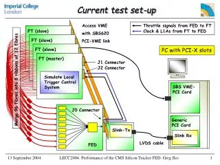
The IDAQ: RMM-Emu USB TFB Interface M. Noy. Imperial College London
RMM-Emu Firmware Structure PC Clock line to TFB Clock/Reset generation Trigger/Reset Line to TFB Trigger Line Interface USB Cable USB EP2 > Wishbone Slaves Wishbone Master EP6 < To TFB Serialiser EP4 > Deserialiser EP8 < From TFB RMM-Emu Firmware Physical connection M. Noy. Imperial College London
RMM-Emu/T2K Test Software • Set of C++ Classes • Lowest two layers are hardware abstraction • Read/Write address space accesses the wishbone bus • 15bit RW address and 16bit data • Configuration packets dealt with underneath • “Unformatted” data pipes • Raw buffer transferred to the upper two end-points • RMMEmuInterface wraps these layers • TFBPacketHandler • Formats the header and payload through member methods • Once done provides access to buffer • Returns a pointer to the buffer directly • Provides a copy method • Written to handle packets both to and from the TFB • T2KTestSystemInterface • Top layer wraps both RMM-Emu layer and TFBPacketHandlers • These are tightly coupled with the firmware • Changing on a daily basis at the moment M. Noy. Imperial College London
RMM-Emu/T2K Test Software UI T2KTestSystemInterface TFBPacketHandler To TFB TFBPacketHandler From TFB Transferable TFB Input TFB Output RMMEmuInterface TFB Packets RMMEmu Config. IDAQHardwareInterface RMMEmu Config. TFB Packets USB Cable USB System UsbDevice M. Noy. Imperial College London
Validation • RMM-Emu Loop-back tests • Serialiser looped to deserialiser • 50cm Ethernet cable used • Packets of pseudorandom data transferred to RMM-Emu • Read back and compared • BER<10-13 • RMM-Emu to TFB • Simple TFB firmware receives packet and sends it back • 50cm Ethernet cable • Pseudorandom numbers sent, read back and checked • BER<10-13 M. Noy. Imperial College London
Clock Buffering, Generation and Timing Adjustment • 100MHz clk from RMM • Buffered at input with DCM • Run-time skew setting managed by FSM • 8 bit number sets tap delay • 10ns/256 ~ 40ps/step • Allows removal of meta-stability • Clk phase adjustment on Tclk (=10ns) scale • Not enough for 9m variation in cable (5.6ns/m for twisted pair) • Separate DES and SER clk domains • Skew can be determined by loopback error detection (not done yet) • 20MHz configuration bus clk speed generated • For address space, slow ctrl, ADC, DAC, readout bus • Time stamp clock • Could just use 100MHz, also possible to generate 125MHz, 150MHz, • Depends on power, design size, … M. Noy. Imperial College London
Packet Based Format - Structure • Idea is to have: • Very light overhead packet-based communications • Inter-packet latency is small (2-3 clock cycles) • Protocol layer implemented on top – lowest level must be flexible • Supports multiple logical channels on one physical channel • Essentially a (first word fall through) FIFO to FIFO interface • Sender and receiver pair can work for upstream and downstream directions • Input and output are 16 bits wide • 5 word header on top of variable length packet • SerDes implementation allows header size to be adjusted • Upstream size not necessarily the same a downstream size • Readout path can have larger or smaller header as required • Raw packet overhead <1% for large packets • Throughput can be ~ 99Mbit/s • Same for up and downstream packets • BUT header words mean slightly different things M. Noy. Imperial College London
Packet Based Format – To TFB • Header • Word 0: bits 15:4 = 12 bit TFB ID • PROM will have unique ID loaded at boot • Packets containing incorrect ID will be rejected • Word 0: bits 3:0 = Logical channel ID • Payload sent to one of 16 input channels • 0=loopback, 1=configuration, 2:15 reserved • Word 1: reserved • Word 2: reserved • Word 3: reserved • Word 4: Payload length • Word 5+: Payload, max length=65535 * 16 bit words • In reality maximum length in use will be something like 1-2 kBytes • TFB packet decoder • Checks validity • Strips off the header • Passes the payload to the channel selected by the channel address M. Noy. Imperial College London
Packet Based Format – From TFB • Header • Word 0: bits 15:4 = 12 bit TFB ID • PROM will have unique ID loaded at boot the this will be in every packet • Word 0: bits 3:0 = Logical channel ID • 0=loopback, 1=configuration/status, 2=data, 3=urgent 4:15 reserved • Word 1: Status • Probably 16 bits, goes in every packet • Word 2: MSW, spill/trigger number (only for physics data) • Word 3: LSW, spill/trigger number (only for physics data) • Word 4: Payload length • Word 5+: Payload, max length=65535 * 16 bit words • In reality maximum length will be something like 1-2 kBytes • Firmware modularity favours smaller packets M. Noy. Imperial College London
TFB Output Stage • Muxing: • Single physical output channel • Round Robin arbiter • Looks at input channels in turn with equal priority • Each input can hold selection indefinitely • Timeout will be added • Each channel has a Packet Formatter • Adds the packet header to the output data stream • Packet formatter requests access to SER • Once granted, the flow control is connected • Underflow and overflow tolerant • Packet formatter holds the output until data packet transferred then it triggers the serialiser M. Noy. Imperial College London
Configuration Interface: TFB Input • TFB has wishbone space • 15bit RW address space, 16bit data bus • Packet structure: • TFBPacketHandler formats with • TFB ID, pipe address and length • Payload formatted as 16 bit words: • Write • Word 0: Write bit & 15bit address • Word 1: Wishbone data length • Word 2: Data packet • Read • Word 0: Read bit & 15bit address • Word 1: Wishbone data length • Requests may be concatenated • Read and write requests may be interleaved M. Noy. Imperial College London
Configuration Interface: TFB Output • TFB formats read request output packets as • Read bit & 15bit address • Wishbone data length • Data packet • This means that concatenated read requests will be returned separately • Example: • TFB ID 0x101, write to register 0x0110 with data 0xaaaa, with read-back check • Header: • 0x1011, 0x0000, 0x0000, 0x0000, 0x0005 • Payload: • 0x8110, 0x0001, 0xaaaa, 0x0110, 0x0001 • Typical TFB Response: • Header • 0x1011, 0x0000, 0x0000, 0x0000, 0x0003 • Payload: • 0x0110, 0x0001, 0xaaaa M. Noy. Imperial College London
TFB Trigger Interface • RMM-Emu has a trigger encoder • TFB has the corresponding decoder • Structure: • 8 trigger vectors • Encoded as start bit + 3 bits on serial line • Seen as 8 independent lines in TFB • 32 bit trigger/spill number • Follows trigger vector • Can be ignored • TFB responds to the trigger after the 4 bit latency • No TFB-Id • Can be broadcast with no protocol overhead • TFB Reset • Triggered if high for more than 50 clks • Currently this is done automatically by the RMM-Emu • Unfortunately, this renders the 8th trigger line unusable M. Noy. Imperial College London
Firmware Architecture Overview & Status Update HV Ctrl Wishbone Master Wishbone bus SERDES DAQ IF Environmental Monitor (?) Output Arbiter Global Mode FSM Clk100 Calibration ClkRF/ Spill Clock Generation Clk200 x4 DIN Clk20 Clk100 DOUT Trip-T Config Spill monitor Wishbone Bus Event Format Trip-T Readout Readout Path Readout Fifos TimeStamp Generation Clock Signal Physical Connection ADC Interface Under design Regional Trigger Done, awaiting validation Global Trigger Done Presently being implemented M. Noy. Imperial College London
Trip-t interfaces • Programming interface • FSM + shift registers, R/W • 8/10 bit packet size • 1 instance • Single select, 1:4 mux on output stage • 2 address bits select trip-t Wishbone bus accessible • Spill Readout interface • FSM with 1:4 fanout • This means that all trip-ts on a board will operate with the same integration period, reset period, number of integration cycles. If this isn’t desirable then now is the time to say so. • Enable mask decides if device used • User will have access to: • Integration time (steps pf 10ns) • Reset time (steps of 10ns) • Number of integration periods per spill (1-24 inclusive) • Trigger once, sequences in-spill and trip-t mux readout • All enabled chips in parallel • Calibration mode is expected to be subset of Spill Readout • Simulation now complete and correct (thanks to input from Mark) M. Noy. Imperial College London
Trip-t & time stamping • Coarse: • 32 bit counter used to generate TS offset relative to spill start • 32 bit wrap time at 100MHz ~ 40 seconds (not 400 years, whoops!) • Fine: • Disc. O/P used • Each drives 2 FPGA pins • Reduce clock speed • Each pin uses DDR reg. with 180o clk phases • Pin pairs have clk pairs offset by 90o phase • Gives Tclk/4 time window • Don’t have to use both • all disc O/P quads sampled on each phase edge • A ‘1’ on any of 4 lines: • Stops sampling of the quad • Triggers a 1 clk pulse aligned with rising edge of clk0 • Loads the complete 64bit fine + 32 bit coarse vector per tript • Reset each bunch • 64 bit enable mask enables disabling of noisy/broken channels • 1 * 96bit input width fifo used per trip-t in raw format • Timestamp encoder • Looks at each channel in turn for every entry in the TS FIFO • Uses difference between n and n+1 • Produces 40 bit output per TS: • 32 bit coarse TS + 2 bit fine TS + 2 bit Trip-T ID + 4 bit channel ID M. Noy. Imperial College London
Physics Data Packets • Packet (Payload) Structure not done yet • Favour smaller packets for modularity of design • Separate for Meta-data, Trip-Ts, time-stamp and ADC data • Recall • Max spill data size (raw) for: • 24 bunch spill • All 4 (trip-t)s enabled • All disc. O/P triggering in every bunch • Is • Timestamp : 4 * 96 * 16 * 24 = 147456 bits • ADC samples: 4 * 10 * 32 * 24 = 30720 • Tot = 178176 bits. (~54% of xc3s1000 block ram) • + overhead (packet header, spill number …) • Envisaged a “requested” readout • RMM requests next packet in a predefined order • Readout FSM waits for next “request” before proceeding • Enables instantaneous data rate reduction • Max total data from 48 TFBs ~ 8Mbit/spill. • We have enough block ram in TFB to do this. M. Noy. Imperial College London
Synchronous Trigger Line to TFB • Trigger input line • 4th line from the RMM • Trigger vector used • 1bit start + 3 bit vector • 8 distinct synchronous trigger lines • Cable difference: • Run-time variable length shift reg at input (0-6 clk cycles) • Clk phase adjust • Tunable such that all TFBs respond at same time • Combined with the timing adjust • Introduces latency of 40ns + max cable delay • Vectors are unassigned at present • Should define (at some point) what is required M. Noy. Imperial College London
In-System Reprogramming • PROM not on current TFB • IC has an in-system update for similar prom on another board • Recall from last time • Require • Safe functional firmware update in system • Use • Design revisioning prom • 2 revisions • R0, read-only • R1, Read/write • Power-on reset circuit always boots R0 • RMM Commands used to: • Reboot to R1 • Reload R1 • Prom JTAG interface wired to FPGA • Some firmware effort required to drive JTAG interface • System updatable and always recoverable • Use for non-volatile board information as well • Hardware design finished • Probably going to work… M. Noy. Imperial College London
Summary & Direction • RMM-Emu produced and functional • TFB back from manufacture • Working minus a few small corrections required • Firmware • Current cycle of • Simulation • synthesis • Validation • Software • Developing in conjunction with FW • Modularity designed to allow transfer of paketiser M. Noy. Imperial College London