Download

1 / 27
270 likes | 280 Vues
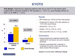
HPK MPPC(Multi Pixel Photon Counter) status. M.Taguchi and T.Nobuhara(Kyoto). Jan.17.2006 @KEK T2K280m meeting. Test Procedure. ・ Observe the raw signal ・ Confirm the fundamental performance ・ gain ・ noise rate ・ crosstalk ・ PDE(photo detection efficiency)

E N D
HPK MPPC(Multi Pixel Photon Counter) status M.Taguchi and T.Nobuhara(Kyoto) Jan.17.2006 @KEK T2K280m meeting
Test Procedure ・ Observe the raw signal ・ Confirm the fundamental performance ・ gain ・ noise rate ・ crosstalk ・ PDE(photo detection efficiency) ・ Linearity ・ Confirm the performance under the real experimental environment - scintillator+WLS fiber+MPPC ・ Laser Test (using BELLE laser system) Already presented at the previous 280m meeting Talk at this meeting
MPPC type used in each measurement We studied the property of HPK100pixel type in detail because we used this type of MPPC in beamtest
Crosstalk measurement Crosstalk‥ photons emitted from one pixel during the Geiger discharge causes the Geiger discharge at neighboring pixels ・Assuming 2p.e noise is caused by crosstalk of 1p.e noise(accidental coincidence of 1p.e noise is negligible) Crosstalk rate = Maximum crosstalk rate is 0.16(HPK100) and 0.25(HPK400) Data taken by random trigger Crosstalk rate Crosstalk rate 0.25 0.16 HPK100 103 0.10 102 HPK400 0.1 10 (V) 48.5 49.0 49.3 49.6 70.3 70.5 70.7 71.0 0.5p.e 1.5p.e 295 448 567 760 74 234 478 800 (kHz)
PDE(photon detection efficiency) ・PDE(photon detection efficiency) is defined as the ratio of the number of output p.e to the number of injected photons PDE=εpixel×QE×εGeiger A ratio of active area to total area (30%~70%) Quantum efficiency of active area (60~80%) Probability of Geiger discharge (60~80%) Depending on wavelength of injected light Depending on bias V Depending on MPPC type Measured the relative PDE to that of PMT with the following set up (about four HPK100 MPPCs)
PDE measurement ・only the light going through 1mmφslit is detected ½ inch PMT WLS fiber ・Scan the MPPC and PMT with moving stage and search the position with maximum light yield The view from this side Blue LED ・The ratio of MPPC p.e to PMT p.e is taken as relative PDE of MPPC to that of PMT MPPC(total area 1mm2) 1mmφslit Y ・ change MPPC bias V MPPC slit ・ light sources are blue LED and wavelength shifting fiber(Y11) x PMT
PDE measurement(cont’d) PDE(MPPC)/PDE(PMT) HPK100#14 Measure PDE at this point ×1.4 green blue 2mm 2mm MPPC X scan MPPC Y scan 70.3 70.5 70.8 71.1 Bias V(V) ・The width of scan is 2mm 294 388 524 687 Noise rate(kHz) ・The max green PDE is about 1.4 times larger than that of PMT and green PDE is larger than blue PDE
PDE measurement(cont’d) ・There is a distance(~0.8mm) between surface cover and active area in HPK’s MPPC ~0.8mm ・so PDE should decrease effectively when using a WLS fiber because light from a WLS fiber spreads at 40° 1mm 40° ½ inch PMT Blue LED ・Measured the effective PDE with this set up about four HPK100e MPPCs(the method of measurement is the same as before) WLS fiber(1mmφ) ・compare the PDE measured in the previous measurement MPPC(total area 1mm2)
PDE measurement(cont’d) PDE(MPPC)/PDE(PMT) HPK100#14 54% PDE 3mm 3mm MPPC X scan MPPC Y scan Effective PDE ・The width of scan becomes 3mm due to spread of light from a WLS fiber Bias V(V) 70.5 70.8 71.1 71.3 388 524 687 864 Noise rate(kHz) ・The decrease of PDE due to spread of light from a WLSF is 40~50% about four HPK100 MPPCs Effective PDE can be increased by improvement of packaging
Linearity measurement(HPK100) ・ inject uniform light from blue LED toPMT and MPPC ・monitor the light injected to MPPC by PMT ・examine the linearity of MPPC output against PMT output ・ linearity depends on the crosstalk rate and the number of pixels, so we measured the linearity at the point that crosstalk rate is 0.03 and 0.2 PMT(1/2 inch PMT) uniform light Blue LED MPPC (HPK100) Set up
Linearity measurement(cont’d) Fired pixel number Difference from the linear extrapolation 10% Crosstalk rate 0.03 Theoretical curve calculated with the crosstalk rate and the number of pixels 20% ・data points agree well with the theoretical curve ・HPK100(100pixel) showed 20% nonlinearity when 35~50p.e are injected (depending on crosstalk rate) injected p.e 50p.e Fired pixel number Difference from the linear extrapolation 10% Crosstalk rate 0.2 20% 35p.e injected p.e injected p.e
Beamtest @KEK in Nov.2005 setup • 0.5~1.4GeV/c • proton & pion • ~100 event/spill • beam size 1x1cm2 Motivation ・Can the light yield for T2K near detector be obtained? beam 64ch MAPMT (as reference) (more than 5p.e for MIP) HPK100e or Russian SiPM 4 layers Scintillator 1.3x2.5x50 cm3 (used in K2K scibar detector) 1mmΦ fiber
Alignment of fiber X ・The X Yposition of active area of HPK’s MPPC is different by each sample,so alignment of fiber is necessary by each sample Y ・Scan the fiber with moving stage and fix the fiber with screws at the point where MPPC signal becomes maximum MPPC screw for fixing fiber fiber About 20% loss of light yield is possible due to misalignment of fiber
Beamtest@KEK(cont’d) We could obtain the light yield for T2K near detector ・The measured PDE including optical contact for HPK100 and Russian SiPM are about 0.7 and 1.0 of PMT, so obtained light yield is consistent with the expectation considering the misalignment of a fiber
Laser test(HPK100) Picture of microscope 100μm microscope Motivation ・study the response of each pixel of MPPC Laser source λ=825nm width 50ps Feed back this information to HPK Laser spot size ≒10μm MPPC We studied Moving stage 1μm pitch (x , y) ・Efficiency distribution within 1pixel ・Uniformity of gain and efficiency in each pixel
Efficiency flat region of 60μm×60μm Efficiency distribution within 1pixel 1pixel ・Scan the laser in the 10mm pitch within 1 pixel(total 100scan) 100μm efficiency laser 1p.e. Efficiency =Ratio of events more than 0.5p.e to total events 0p.e. 100μm 100μm 0.5p.e.
Response of each pixel y ・Inject laser to the center of each pixel and study the response of each pixel x Total 100pixel Relative gain Relative efficiency 1.06 1.04 Response of each pixel is uniform! RMS/mean=3.6% RMS/mean=2.5% 0.96 0.92 y y x x
Summary About HPK100pixel MPPC • The green PDE is larger than that of PMT • Light yield for MIP is 10~13p.e (at the point that noise rate and gain satisfy T2K requirement) • Response of each pixel is uniform Show 20% nonlinearity when 35~50p.e are injected → need more than 200pixel The loss of light yield due to spread of light from a WLS fiber is 40~50% → can be improved by packaging
Future plan • Test the new samples which recently we got (HPK say these have higher PDE than others) • Study the response of each pixel more in detail with the laser system for MPPC @KEK
MPPC(Multi pixel photon coutner) MPPC characters: • 100~1000 APD pixel in 1mm2 • Each pixel operates as Geiger mode (independent of input light) • The output is a sum of all the APD signals • Compact • Low-cost • Insensitive to the magnetic field • Low bias voltage :30~75V • High gain:105~107
Signal and p.e peak HPK100a V=48V 2p.e 1p.e 30p.e 0p.e Increasing the injected light ・We can count the peak up to 4p.e ・the interval between each peak completes by 4%
Summary of gain measuremnt RUS#14 ・T=20° RUS#23 RUS#20 ・Gain=3×10⁵~2×10⁷ ・The (dG/dV)depends on the capacitance of pixel RUS#22 43 Bias V 35 HPK100f HPK100d HPK100a HPK100e HPK400b Bias V HPK1600a Bias V 47 49 70 74.5
Summary of gain measurement ・dG/dV depends on capacitance of pixel ・Typical gain 7×10⁵~6×10⁶ @T=20° gain gain gain Russian HPK100e HPK400b 2×10⁶ 6×10⁶ 5×10⁵ 70 35 36 71 47.5 49.5 Bias V Bias V Bias V
Summary of noise rate measurement 106 106 noise rate (Hz) noise rate(Hz) HPK100f HPK100d RUS#14 RUS#23 HPK100e HPK1600a RUS#20 RUS#22 35 43 70 74 bias voltage (V) bias voltage (V) 0.5p.e threshold by pulse height @T=20° 0.5p.e threshold by charge (in progress) 1.5p.e threshold by pulse height
Summary of noise rate measurement ・Maximum noise rate~ a few MHz ・Noise rate increases by an order of magnitude with increasing bias V by 1V 0.5p.e threshold 1.5p.e threshold Noise rate (Hz) Noise rate (Hz) Noise rate (Hz) HPK100e HPK400b Russian 106 106 106 104 104 104 35 37 70 71 48 50 Bias V Bias V Bias V
P/π separation is possible P/π separation 1.2GeV 1.0GeV 0.9GeV 1.2GeV 1.0GeV 0.9GeV π p 0.8GeV 0.8GeV 0.7GeV 0.6GeV 0.7GeV 0.6GeV 0.5GeV 0.5GeV MPPC MAPMT