Download

1 / 32
320 likes | 338 Vues
This paper presents a new method for 2D laser scan matching using polar coordinates, which improves the speed and accuracy of the Iterative Closest Point (ICP) method. The Polar Scan Matching (PSM) approach matches scans based on bearing, avoiding the need to search for point correspondences. The paper demonstrates the implementation of SLAM using PSM.

E N D
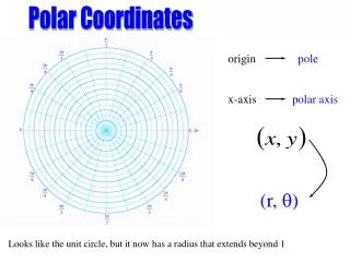
Laser Scan Matching in Polar Coordinates with Application to SLAM Albert Diosi Lindsay Kleeman ARC Centre for Perceptive and Intelligent Machines in Complex Environments Dept. of Electrical and Computer Systems Engineering Monash University, Australia www.pimce.edu.au
Overview • New 2D laser scan match method presented. • Polar Scan Matching (PSM) – point to point scan match approach in polar coords. • Avoids searching for point correspondences by simply matching bearing. • Faster than Iterated Closest Point (ICP) method. • SLAM implementation demonstrated with PSM.
Previous Work • Scan matching can be categorized by the association method: • Feature to feature, • eg line segments [Gutman PhD 2000] or range extrema [Lingemann et al IROS 2004] • Point to feature. • Eg [Cox IEEE R&A 1991] • Point to point. • Least dependent on environment and chosen here.
Point to Point Literature • Iterative Closest Point (ICP) • [Besl and McKay IEEE PAMI 1992] • Iterative Matching Range Point (IMRP) • [Lu and Milios JIRS 1997] • Iterative Dual Correpondence (IDC) • Uses IMRP for rotation and ICP for translation in each iteration [Lu and Milios JIRS 1997]. • One iteration required if associations known. • Requires 15-20 iterations in practice since correct associations are initially unknown.
Associations are the Key! • IDC needs to associate each point in the new scan with one in the reference scan. • Each point can require all points in other scan to be checked => O(n2) computation. • In practice some search restrictions can reduce this computation. • Polar Scan Matching (PSM) in this paper just needs to check the same angle of a transformed scan.
Polar Scan Matching • PSM has these steps: • Scan Preprocessing • Scan Projection • Translation Estimation • Orientation Estimation • Error Covariance Estimation
PSM Preprocessing • Points not suitable for matching are removed by median filtering: • Chair and people’s legs • Mixed pixels caused by range discontinuities • Maximum range measurements (ie no object) removed by thresholding
Segmentation of objects • Interpolation between distinct objects avoided • Possibility of tracking and deleting moving objects between successive scans. • New segment when consecutive difference > 20 cm • Same segment when 3 measurements on nearly same polar line.
Scan Projection • Transform current scan into reference scan frame. Current scan transformed To reference frame Reference scan origin
Points are occluded by nearerscan points. Ranges at reference scan positions are calculated by linear interpolation in polar coords.Shown as Occlusion handled by over-writing further ranges. Ranges are tagged invisible if in opposite order Scan Projection (cont’d)
Translation Estimation • Aim is to find new that minimises • Association of ranges trivial – just use the bearing. • Linearized regression used over a few iterations – see paper for details. Sigmoid weight that favourssmall errors [Dudek2000] current projected reference
Orientation Estimation • Change of orientation is simply a shift in polar coords. • The shift with min absolute average range error chosen. • Parabolic interpolation applied to find sub angle sample estimate using 3 samples centred on min.
Error behaviour – simulated data Scan initial mismatch
Error Estimation • If correct associations are known, error covariance can be estimated from the linear regression analysis. • In practice this covariance is optimistic since inevitable errors of association and moving objects cause larger errors. • Heuristic diagonal covariance used based on average range residual except in “corridors”. • Corridors are identified by the variance of orientations of lines segments < threshold. • Non-diagonal covariance used for corridors.
Corridor Drift • Corridor environments tend to cause biased matches:
Ground Truth Experiments • Various positions and orientations of a laser template were marked on a sheet. • Measurements from known relative positions of the sheet were taken of different environments using Sick LMS 200 • Displacements of 80 cm and up to 27°
cm deg Iteration number msec PSM Error Behaviour X error o Y error Angle error + Note corridor scene fails to converge
cm deg Iteration number msec ICP Error behaviour X error o Y error Angle error + Note corridor scene fails to converge
Regions of Convergence o = no convergence o = incorrect convergence point + = true shift point + + PSM ICP
Areas of Convergence • Averaged over 10 scenes with initial 12º offset • Convergence defined as within 10 cm and 2º of true position • PSM converged from 2.99 m2 • ICP converged from 2.80 m2
SLAM • EKF based SLAM implemented similar to [Bosse,Newman,Leonard &Teller IJRR2004] • Laser scans are used as landmarks. • New scans stored every 1 m of robot and SLAM updated every 1 m or 15º • Scan matching acts as a landmark measurement. • Odometry used over short distances.
10 meters Polar Scan Matching SLAM
10 meters Iterative Closest Point (ICP) SLAM
Polar Scan Matching SLAM Video (2 min) • Average scan match time during SLAM on a Celeron 900 MHz laptop was: • ICP: 65 matches successful at 12.6 msec each. • PSM: 100 matches successful at 3.1 msec each.
Conclusions and Future Work • Presented a new scan match method that works in native Polar coordinates called Polar Scan Matching – code will be made available on www – see paper. • Removal of occluding points simply done based on further range. • PSM ~4 times faster than ICP. • PSM SLAM successfully demonstrated.
Future Work • Comparison of PSM with IDC and other scan matching approaches. • Tracking and removal of moving segments to improve robustness. • Funding of the ARC Centre for Perceptive and Intelligent Machines in Complex Environments is acknowledged.