Download
1 / 1
10 likes | 235 Vues
Envelope Amplifier for ERR and ET Architectures using RF Si-LDMOS Technology. M. Patiño.

E N D
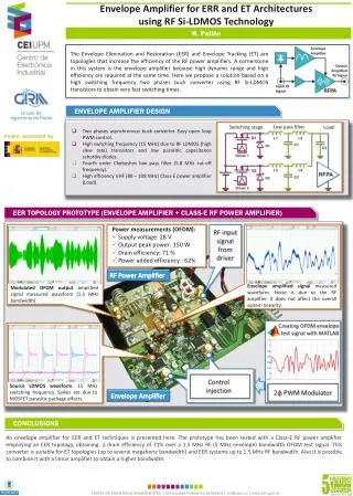
Envelope Amplifier for ERR and ET Architectures using RF Si-LDMOS Technology M. Patiño The Envelope Elimination and Restoration (EER) and Envelope Tracking (ET) are topologies that increase the efficiency of the RF power amplifiers. A cornerstone in this system is the envelope amplifier because high dynamic range and high efficiency are required at the same time. Here we propose a solution based on a high switching frequency two phases buck converter using RF Si-LDMOS transistors to obtain very fast switching times. ENVELOPE AMPLIFIER DESIGN Grupo deIngeniería de Radio Low pass filter Switching stage Load • Two phases asynchronous buck converter. Easy open loop PWM control. • High switching frequency (15 MHz) due to RF LDMOS (high slew rate) transistors and low parasitic capacitance schottky diodes. • Fourth order Chebyshev low pass filter (5.8 MHz cut-off frequency). • High efficiency VHF (88 – 108 MHz) Class-E power amplifier (Load). Project sponsored by EER TOPOLOGY PROTOTYPE (ENVELOPE AMPLIFIER + CLASS-E RF POWER AMPLIFIER) • Power measurements (OFDM): • Supply voltage: 28 V • Output peak power: 150 W • Drain efficiency: 71 % • Power added efficiency : 62% RF input signal from driver RF Power Amplifier Envelopeamplified signal measured waveform. Noise is due to the RF amplifier. It does not affect the overall system linearity. Modulated OFDM output amplified signal measured waveform (1.5 MHz bandwidth). Creating OFDM envelope test signal with MATLAB Control injection Source LDMOS waveform. 15 MHz switching frequency. Spikes are due to MOSFET parasitic package effects. 2φ PWM Modulator Envelope Amplifier CONCLUSIONS An envelope amplifier for EER and ET techniques is presented here. The prototype has been tested with a Class-E RF power amplifier employing an EER topology, obtaining a drain efficiency of 71% over a 1.5 MHz RF (5 MHz envelope) bandwidth OFDM test signal. This converter is suitable for ET topologies (up to several megahertz bandwidth) and EER systems up to 1.5 MHz RF bandwidth. Also it is possible to combine it with a linear amplifier to obtain a higher bandwidth.