Download
1 / 9
90 likes | 612 Vues
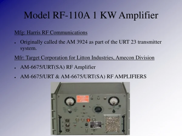
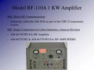
Model RF-110A 1 KW Amplifier. Mfg: Harris RF Communications Originally called the AM 3924 as part of the URT 23 transmitter system. Mfr: Target Corporation for Litton Industries, Amecon Division AM-6675/URT(SA) RF Amplifier AM-6675/URT & AM-6675/URT(SA) RF AMPLIFIERS. `.

E N D
Model RF-110A 1 KW Amplifier Mfg: Harris RF Communications • Originally called the AM 3924 as part of the URT 23 transmitter system. Mfr: Target Corporation for Litton Industries, Amecon Division • AM-6675/URT(SA) RF Amplifier • AM-6675/URT & AM-6675/URT(SA) RF AMPLIFIERS `
Full System Includes RF-110A 1 KW Power Amplifier with RF-124 Power Supply
All mode – SSB, AME (compatible AM) CW, ISB and FSK. • 1 KW PEP out – USB, LSB, ISB & compatible AM (350 w. of carrier.) • 1 KW avg. power output – CW, FSK and FAX emissions • Input: 100 mW nominal (25 mW to 150 mW) to a pair of 8122 tetrodes running in class A. • 8122s provide 10 watts of drive to 4CX1500B tetrodes finals (AB 1) connected in parallel. 20 db gain per stage, 40 db overall. • MFJ 259B antenna analyzer testing of input actually drove amplifier to 300 watts output. • Front panel control allows power output adjustment down to 10W. • No mismatch worry – amplifier senses the SWR and reduces output when it exceeds 4:1. • Amplifier and power supply have redundant interlocks throughout. • Extensive protection and overload circuts prevent damage to the amplifier and finals.
Built in APC and PPC which automatically limit average and peak output. • The APC can be used to provide feedback to a transmitter. • The PPC provides internal amplifier feedback to the 8122 stage limiting output to preset level via single potentiometer adjustment. (I have adjusted mine to 1500 W output.) • No need for a matched pair of 4CX1500Bs – finals are balanced via selection of screen voltages using taps provided on a zener diode stack. External control items needed to run amplifier • +28 volt input places RF amplifier in standby condition. • +20 volt input places RF amplifier in operate condition. • Grounded input places RF amplifier in keyed condition. • Grounded input alters APC and PPC for compatibility with CW/FSK mode of operation.
This linear RF power amplifier covers a frequency range of 2 to 30 Mhz in 19 band segments – No tuning of any kind is required. Select band and go! • Operates fine on the 160 meter band (1.8 – 2.0 MHz.) • Amplifier input is also 50 ohm and band segment tuned.
The RF-124 Power Supply Input power: 208-242 VAC, 4500 W, 50/60Hz, Single Phase, 18.6 – 21.6 amps. Overall size: 17 3/8” W x 19” D x 12 1/4” H Weight: 200 lbs Two additional power supplies available: • RF-111A – 115 VAC, 400 Hz, three phase (fits inside of RF-110A) • RF-112A – 208/440 VAC, 50/60 Hz, three phase, external Power Supply Output Voltages: +2250 Vdc at 1.2A (for final amplifier plates.) +500 Vdc at 0.9A (for final amplifier screens, driver plates, and screens.) 115 VAC, 400 Hz, single-phase, square wave, 70 watts (for blower and time meter motors.) 115 VAC, 60 Hz, single-phase, 1.85A (for band change motor and external requirements.)
From N2BC Web Site I had a very pleasant 'discussion' via eMail with Dave Russell, W2DMR. Dave worked on the RF-110 and has been a big help in getting mine on the air. Dave passed along this brief history: Maybe a little history of the amplifier is in order, if you haven't caught up with it. Originally this amplifier was designed for the US Navy and carried the designation of AM 3924 and was part of the URT 23 transmitter system. In the Navy version there were 2 different power supplies, an external 50/60 Hz 3 phase supply and a 400 Hz supply that could be installed inside the amplifier (I believe the 50/60 Hz supply was designated PP 3916.) There was also an exciter (T827) and an automatic antenna coupler for shipboard whip antennas. Design of all this stuff took place in 1967 through 1968 and the first production run was for 1200 systems. Towards the end of the design phase, a couple of the founders of the company were going to go on a Dxpedition to some islands off the west coast of Mexico, and a couple of us thought it would be neat if we could build a single phase power supply for the amplifier. We did, and built several which were taken on the expedition along with the amplifiers and couplers. After we got into the production phase it was decided to build a commercial version, and it and the navy version became quite a good product line.