Frame Structures including SAP2000 (rev. ed.), by Wolfgang Schueller
2.79k likes | 3.61k Vues
Refer to:(1) The Design of Building Structures (Vol.1, Vol. 2), rev. ed., PDF eBook by Wolfgang Schueller, 2016, published originally by Prentice Hall, 1996, (2) Building Support Structures, Analysis and Design with SAP2000 Software, 2nd ed., eBook by Wolfgang Schueller, 2015.

Frame Structures including SAP2000 (rev. ed.), by Wolfgang Schueller
E N D
Presentation Transcript
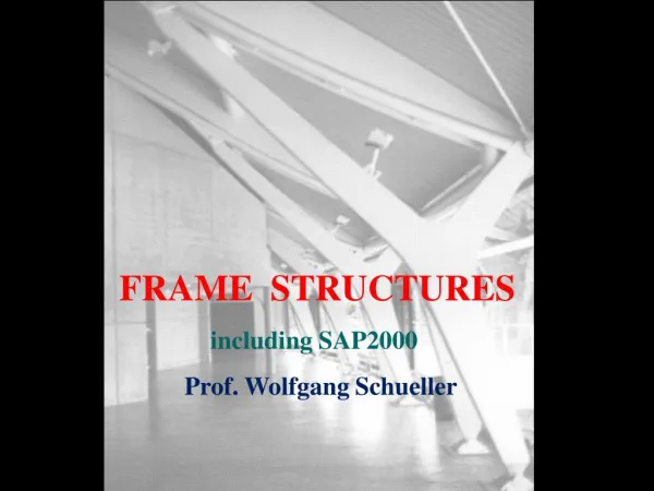
FRAME STRUCTURES including SAP2000 Prof. Wolfgang Schueller
For SAP2000 problem solutions refer to “Wolfgang Schueller: Building Support Structures – examples model files”: https://wiki.csiamerica.com/display/sap2000/Wolfgang+Schueller%3A+Building+Su pport+Structures+- If you do not have the SAP2000 program get it from CSI. Students should request technical support from their professors, who can contact CSI if necessary, to obtain the latest limited capacity (100 nodes) student version demo for SAP2000; CSI does not provide technical support directly to students. The reader may also be interested in the Eval uation version of SAP2000; there is no capacity limitation, but one cannot print or export/import from it and it cannot be read in the commercial version. (http://www.csiamerica.com/support/downloads) See also, ((1) The Design of Building Structures (Vol.1, Vol. 2), rev. ed., PDF eBook by Wolfgang Schueller, 2016, published originally by Prentice Hall, 1996, (2) Building Support Structures, Analysis and Design with SAP2000 Software, 2nd ed., eBook by Wolfgang Schueller, 2015. The SAP2000V15 Examples and Problems SDB files are available on the Computers & Structures, Inc. (CSI) website: http://www.csiamerica.com/go/schueller
Structure Systems & Structure Behavior INTRODUCTION TO STRUCTURAL CONCEPTS SKELETON STRUCTURES Axial Systems Beams Frames Arches Cable-supported Structures SURFACE STRUCTURES Membranes: beams, walls Plates: slabs Hard shells Soft shells: tensile membranes Hybrid tensile surface systems: tensegrity SPACE FRAMES LATERAL STABILITY OF STRUCTURES • • • • • • • • • •
A X IA L S T R U C T U R E S Y S T E M S TENSILE MEMBERS COMPRESSIVE MEMBERS L I NE E L E M E NT S BEAMS F LE X U R A L S T R U C T U R E S Y S T E M S F LE X U R A L-A X IA L S T R U C T U R E S Y S T E M S BEAM-COLUMN MEMBERS FRAMES T E N S ILE M E M BR A N E S SOFT SHELLS SUR F A CE E L E M E NT S MEMBRANE FORCES P LA T E S SLABS, MEMBRANE BENDING and TWISTING S H E LLS RIGID SHELLS
FRAMES are flexural-axial systems in contrast to hinged trusses, which are axial systems, and isolated beams, which are flexural systems. Continuos frames are flexural-axial systems as identified by beam-column behavior that includes the effects of biaxial bending, torsion, axial deformation, and biaxial shear deformations. Here, two-dimensional skeleton structures composed of linear elements are briefly investigated. The most common group of planar structure systems includes post-beam structures, bent and folded beams, rectangular portal frames, cantilever frames, braced frames, pitched frames, arches, and so on.
These structures may form short-span or long-span, single-story or multi-story, single-bay or multi-bay systems. They range from low-rise to single, open, large volume buildings cellular massive buildings skyscrapers. Frames may be of regular or irregular geometry Primary emphasis here is on the investigation of simple, but common single-story enclosure systems to develop a feeling for the behavior of structures under gravity and lateral loads. Investigated are the • response and effect of the frame profile on uniform gravity action and on lateral loading. • the magnitude of the internal member forces is determined so that the computer results can be checked.
Typical examples of frame architecture are shown on the following slides. First some historical important cases are shown.
Barcelona Coffee Table, 1929, Mies van der Rohe
mr side chair, 1927, Ludwig Mies van der Rohe
Wassili Chair, Bauhaus School, Weimar/Dessau, Germany, 1925, Marcel Breuer Designer
Pertoia Side Chair (1952) and Diamond Chair (1950), Harry Bertoia Designer
Aluminum Lounge Chair without arms, 1958, Charles and Ray Eames designers for Herman Miller
GF David Rowland 40/4 Stacking Chair, 1964
Cummins Engine Component Plant , Columbus, IN, 1965, Roche & Dinkeloo
Reliance Controls factory, Swindon, 1967, Team 4, Anthony Hunt Struct. Eng
Athletics Building, Phillips Exeter Academy, Exeter, NH, 1970, Kallmann & McKinnel Arch, Le Messurier Struct. Eng.
Facep constructive system, Fiat car distributor, Bussolengo, 1976, Italy, Angelo Mangiarotti Arch
Municipal Stadium, Florence, 1932, Pier Luigi Nervi
St Alexander's Church, Morrisonville, New York, Jeremiah Oosterbaan Arch
Lake Shore Drive Apts, Chicago, 1951, Ludwig Mies van der Rohe Arch
Economist Building, London, England, 1962, Alison and Peter Smithson Arch
Museum of Modern Art, Rio de Janeiro, Brazil, 1958, Alfonso Eduardo Reidy
Ozeaneum Stralsund, Stralsund, Germany, 2008, Stefan Behnisch Arch, Schweitzer GmbH Struct Eng
Richard J. Klarchek Information Commons, Loyola University Chicago, 2007, Solomon Cordwell Buenz Arch, Halvorson and Partners Striuct.
Richard J. Klarchek Information Commons, Loyola University Chicago, 2007, Solomon Cordwell Buenz, Halvorson and Partners Striuct.
Ningbo downtown, 2002, Qingyun Ma Arch
Richard J. Klarchek Information Commons, Loyola University Chicago, 2007, Solomon Cordwell Buenz, Halvorson and Partners Striuct.
House II (Falk House), Hardwick, Vermont, 1969, Peter Eisenman Arch
Shipping Container Restaurant, Seguin Island, Paris, France, 2013, Jean Nouvel Arch
The following sequence of topics is used: Uniform Loading on Inclined Members Simple Folded and Bent Beams Single-bay Frames Three-Hinged Frames Indeterminate Frames Cantilever Frames Braced frames Pitched Frames Multi-bay Frames Multi-bay, Single-Story Frames Multi -Story Frames Vierendeel Trusses
The loading on a simply supported inclined beam is investigated in with a pin support at the base and a roller support at the top, which however may have different orientations. The typical gravity loading of an inclined member consists of the dead load wDacting along the structure, and the live load wL, which is usually given by codes on the horizontal projection of the structure (a). To determine the maximum moment, it is convenient to transfer the dead load to the horizontal projection of the beam (b), since the maximum moment of a simply supported inclined beam is equal to that for an equivalent beam on the horizontal projection carrying the same loading as the inclined beam. In other words, the moment is independent of beam slope and support conditions. The shear depends on the beam inclination but not on the orientation of the top support. It is equal to the shear of the beam on the horizontal projection multiplied by cosθ. The parallel load components cause axial forces along the beam and are equal to the load on the horizontal projection multiplied by sinθ. The axial force flow depends on the beam inclination and on the reaction condition of the top support. The uniform lateral loading case is analogous to the uniform gravity loading case; just visualize the span L and height h to be exchanged. For example, the maximum moment due to the wind pressure q on the vertical projection of the beam is, The fact that the moment is independent of the geometry of the bent or folded beam for vertical support conditions, is demonstrated in the drawing. Various folded beam systems are investigated in the following drawing ranging from a simple inclined beam (B), a stair (E.), to other roof frame shapes. Notice SAP automatically transfers the loads from the projection to an equivalent load along the member!
wL + wD/cosθ wD + wLcosθ wL wD h L/cosθ wDcos θ + wLcos2θ θ L The parallel load component causes axial force action in the member: (wD + wLcosθ) sinθ and from the perpendicular load component the shear is determined: (wD + wLcosθ) cosθ
wcosθ = 0.93 k/ft -7.94 ft-k 50 ft-k 34.46 ft-k 50 ft-k 49.70 ft-k 50 ft-k
1 k/ft -5.76 ft-k 53.85 ft-k 37.69 ft-k 53.85 ft-k 54.11 ft-k 53.85 ft-k
wsinθ = 0.37 k/ft 7.94 ft-k 8 ft-k 13.61 ft-k 8 ft-k 15.87 ft-k 8 ft-k
Folded Beam Structures b a d c f e g The magnitude of the maximum moment for simple folded or bent beams under uniform vertical loads does not change when the load is applied on the horizontal projection of the beams. Naturally, the magnitude of the axial forces will change.
a b c d f e g b a Mmax = wL2/8 d c f e g
MEMBER ORIENTATION Is defined by local coordinate system Each part of the structure (e.g. joint, element) has its own LOCAL coordinate system 1-2-3. The joint local coordinate system is normally the same as the global X-Y-Z coordinate system. For the elements, one of the element local axes is determined by the geometry of the individual element; the orientation of the remaining two axes is defined by specifying a single angle of rotation. For frame elements, for example, the local axis 1 is always the longitudinal axis of the element with the positive direction from I to J. The default orientation of the local 1-2 plane in SAP is taken to be vertical (i.e. parallel to the Z-axis). The local 3-axis is always horizontal (i.e. lies in the X-Y plane).


![[PDF] Free Download The Intelligent Investor, Rev. Ed By Benjamin Graham](https://cdn5.slideserve.com/9893893/slide1-dt.jpg)