Modelling of bubble-particle hydrodynamics
330 likes | 819 Vues
Modelling of bubble-particle hydrodynamics. Chemical and Materials Engineering University of Alberta. Outline. Background M ilestone Cavitation model Cavitation experiments Population balance model Population balance experiments Future work. Background.

Modelling of bubble-particle hydrodynamics
E N D
Presentation Transcript
Modelling of bubble-particle hydrodynamics Chemical and Materials Engineering University of Alberta
Outline • Background • Milestone • Cavitation model • Cavitation experiments • Population balance model • Population balance experiments • Future work
Background • Objective: develop a system for enhancing fine particle flotation using microbubbles generated by cavitation • Mechanism proposed by Zhou et al. 1997 • Hydrophobic particle surface in water is a good nucleation sites for cavity generation particle particle tiny bubble tiny bubble Flotation-sized bubbles Enhanced coagulation by Bubble bridging Two stage attachment
Agitator Liquid filled all the way up to here to prevent entrainment of air Visualization Cell Laser Light Source Pump Computer CCD HIA Cell Electrodes HIA cell
Milestone • Develop a model for cavitation using CFD • Apply the cavitation model in a high intensity agitation system • Determine critical variables for hydrodynamic cavitation • Determine bubble size distribution using population balance equations • Measure of bubble size distribution • Couple the cavitation, population balance equations and flow equations • Floatation recovery studies
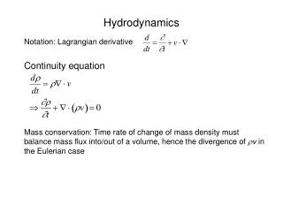
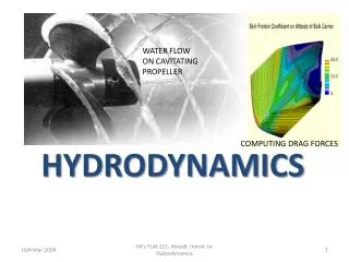
Cavitation model • Multiphase flow • Continuity equation for mixture • Momentum equation for mixture • Cavitation model for vapor phase • Mass transfer - growth of cavitation bubbles using Rayleigh-Plesset equation • Assumption- spherical bubbles
Cavitation model • Full cavitation model • Vapor transport equation Evaporation rate term Condensation rate term When Pv ≥ P When Pv ≤ P Singhal et al. (2002): Ce=0.02, Cc=0.01
HIA Cell CFD modelling CFD Modelling of cavitation is performed for the laboratory HIA cell for different impeller speeds and different dissolved gas content.
HIA Cell CFD modelling • Tetrahedral meshing • Steady flow • B.C.- rpm of impeller • Multiple Reference Frame Model Working fluid: Water at 200C and 1 atm pressure
Volume fraction of vapor Contours of pressure and volume fraction of vapour in the HIA cell Pressure
Dissipation Contours of turbulent kinetic energy and dissipation rate in the HIA cell Turbulent kinetic energy
Geometries • Orifice (R/r=2,3) • Venturi (R/r=2) R r R r
Pressure profile in orifice and venturi Sharp orifice Venturi
Vapor fraction vs. inlet velocity • Total vapor fraction in the geometry for orifice with R/r =2 and 3 vs. inlet velocity
CFD analysis in orifice R/r=3 • Velocity contours in orifice (R/r=3) • Pressure profile • Vapor fraction contours Inlet velocity= 4 m/s Max velocity= 51 m/s Max pressure= 1.14 MPa Min pressure= -98 kPa Max vapor fraction= 0.92
CFD analysis in orifice R/r=3 • Velocity contours in orifice (R/r=3) • Pressure profile • Vapor fraction contours Inlet velocity= 4 m/s Max velocity= 51 m/s Max pressure= 1.14 MPa Min pressure= -98 kPa Max vapor fraction= 0.92
Validation of cavitation model • Orifice • Venturi
Experimental setup • 35 m long • ID= 1 inch • Variable speed slurry pump • Velocity range: 0-6 m/s for 1 inch ID tube
Vapour fraction measurements • Conductivity cell: C: Specific conductivity of the solution G: Measured conductivity of the solution L: Distance between two plates A: area of the plates L/A: cell constant http://www.coleparmer.ca/techinfo/techinfo.asp?htmlfile=Conductivity.htm&ID=78
Population balance model • Transport equation for the bubble number density function, n: • Source term, S, accounts for nucleation, breakage and coalescence (aggregation) of bubbles (particles).
Population balance model Bubbles are divided into a finite number of bins. Equations solved for each group (bin). Nucleation is given by the cavitation model. Breakage and Coalescence/Aggregation models Coupled to the flow equations to determine the local flow hydrodynamic conditions. A User Defined Function (UDF) is used to couple cavitation mass transfer to Population Balance Model
Population balance model Determine number of bins Determine best breakage/coalescence model Require parameters in these models
PBM experiments • Using a venturi to investigate the bubble formation • Investigating a method to measure bubble size distribution • FBRM • (Dp>0.5 micron) • ZetaPALS • (sampling) • Microscopic methods
Future Work Implement physical experiments to evaluate parameters in population balance model Use UDF in Fluent to model the generation of bubbles Implement the population balance in a bubble-particle environment Determine bubble-particle and particle-particle collision rate (frequency) and efficiency model parameters {experiments} Comprehensive model for flotation involving in-situ bubble generation, bubble-particle interaction and the ultimate flotation recovery. Parametric study
Acknowledgements • Financial support for this work from: • NSERC-CAMIRO CRD Grant on Fine Particle Flotation • NSERC-industrial Research Chair Program in Oil Sands Engineering.