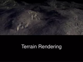
3D Graphics Rendering and Terrain Modeling
590 likes | 757 Vues
3D Graphics Rendering and Terrain Modeling. Technology and Historical Overview. By Ricardo Veguilla. Overview. Introduction to 3D Computer Graphics OpenGL SGI vs Linux 3D Animation Terrain Modeler: Project Status. Introduction to 3d Computer Graphics.

3D Graphics Rendering and Terrain Modeling
E N D
Presentation Transcript
3D Graphics Rendering and Terrain Modeling Technology and Historical Overview By Ricardo Veguilla
Overview • Introduction to 3D Computer Graphics • OpenGL • SGI vs Linux • 3D Animation • Terrain Modeler: Project Status
Introduction to 3d Computer Graphics • 3D computer graphics is the science, study, and method of projecting a mathematical representation of 3D objects onto a 2D image using visual tricks such as perspective and shading to simulate the eye's perception of those objects.
3D Graphics and Physics • 3D graphic software is largely based on simulating physical interactions. • Generally: • Space relations. • Light interactions. • In particular cases: • Material properties. • Object Movement.
Goals of 3D computers graphics • Practical goal: Visualization - to generate images (usually of recognizable subjects) that are useful in some way. • Ideal goal: Photorealism - to produce images indistinguishable from photographs.
Components of a 3D Graphic System • 3D Modeling: • A way to describe the 3D world or scene, which is composed of mathematical representations of 3D objects called models. • 3D Rendering: • A mechanism responsible for producing a 2D image from 3D models.
3D Modeling • Simple 3D objects can be modeled using mathematical equations operating in the 3-dimensional Cartesian coordinate system. • Example: the equation x2 + y2 + z2 = r2 is a model of a perfect sphere with radius r.
Modeling considerations • Pure mathematical equations to represent 3D objects requires a great deal of computing power • Impractical for real-time applications such as games or interactive simulations.
Alternatives: Polygon Models • Modeling objects by sampling only certain points on the object, retaining no data about the curvature in between • More efficient, but less detailed.
Alternatives: Texture Mapping • Technique used to add surface color detail without increasing the complexity of a model. • An image is mapped to the surface of a model.
From 3D models to 2D images • A 3D world or scene is composed of collection of 3d models • Three different coordinates systems (or spaces) are defined for different model related operations: • Object Space • World Space • Screen Space
Object Space • The coordinate system in which a specific 3D object is defined. • Each object usually have its own object space with the origin at the object's center • The object center is the point about which the object is moved and rotated.
World Space • World space is the coordinate system of the 3D world to be rendered. • The position and orientation of all the models are defined relative to the center of the world space. • The position and orientation of the virtual camera is also defined relative to the world space.
Screen Space • 2D space that represents the boundaries of the image to be produced. • Many optimization techniques are performed on screen space.
Mathematics of 3D graphics • 3D operations like translation, rotation and scaling are performed using matrices and lineal algebra. • Each operation is performed by multiplying the 3D vertices by a specific transformation matrix.
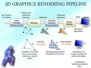
3D Rendering • The process of taking the mathematical model of the world and producing the output image. • The core of the rendering process involves projecting the 3D models onto a 2D image plane.
Types of Rendering Algorithms • Two general approaches: • Pixel-oriented rendering: • Ray tracers • Polygon-oriented rendering: • Scan-line renderers
Ray tracers • Operates by tracing theoretical light rays as they intersect objects in the scene and the projection plane.
Ray tracer limitations • Processor intensive. A full ray tracer is impractical for real-time applications. • Does not take into account inter-reflections of diffuse light, resulting in hard shadows.
Radiosity • Technique that models the inter-reflections of diffuse light between surfaces of the world or environment. • Produces more photorealistic illumination and shadows.
Scan-line renderers • Operate on an object-by-object basis, directly drawing each polygon to the screen. • Requires all objects – including those modeled with continuous curvature – to be tessellated into polygons. • Polygons are eventually tessellated into pixels.
Illumination for scan-line renderers • Lighting and shading is calculated using the normal vector. • The color is linearly interpolated across the polygon surface.
Common shading techniques scan-line renderer • Flat shading • Gouraud Shading • Phong Shading
Flat Shading • The color of the polygon is calculated at the center of the polygon by using the normal vector. • The complete polygon surface is uniformly lighted.
Gouraud Shading • A normal vector is calculated at each vertex. • Color is calculated for each vertex and interpolated across the polygon
Phong Shading • The normal vectors are interpolated across the surface of the polygon • The color of each point within the polygon is calculated from its corresponding normal vector
Viewing frustum • Segment of the 3D world to be rendered • Objects outside the viewing volume are ignored.
Hidden surface determination • Not all objects inside the viewing frustum are always visible from the point of view of the camera. • Not all polygons of a particular object are visible from the point of view of the camera. • Common Techniques • Painters Algorithm • Z-Buffering
Painter’s Algorithm • Polygon-oriented. • All the polygons are sorted by their depth and then displayed in this order.
Z-Buffering • Pixel-oriented. • When multiple objects overlap (from the point of view of the camera) on a particular pixel, only the value of the pixel closest to the camera is used. • Implemented by saving the depth value of each displayed pixel in a buffer, and comparing the depth of each new overlapping pixel against the value in the buffer.
Perspective Projection • Projects the 3D world to a 2D image
OpenGL – The Open Graphics Language • De facto Application Programming Interface (API) for cross-platform development of 3D graphics applications. • Implementations available for all major Operating Systems and hardware platforms. • Support for hardware accelerated 3D rendering. • Scalable, high-level, easy to use, well documented.
History of OpenGL • Originally released by SGI in the early 90s. • Descendant of IRIX GL. • Previous 3D graphics APIs were generally platform dependant. • Born out of market pressure for a cross-platform 3D API during the late 80s.
OpenGL - Code Example • How to define a triangle: glBegin (GL_TRIANGLES); glVertex (0,0,0); glVertex (1,1,0); glVertex (2,0,0); glEnd ();
Development with OpenGL • OpenGL API designed only for drawing images. • Auxiliary visual toolkits are required for developing OpenGL applications for modern windowed desktop environments. • Potential options: • GLUT, SDL, GTK+
Potential Auxiliary Toolkits • GLUT: Specifically designed for developing OpenGL demo applications. • SDL (Simple DirectMedia Layer): Library for multimedia and game development. • GTK+: General purpose toolkit for creating graphical user interfaces with OpenGL extensions available.
SGI vs Linux VS
SGI vs Linux • Linux is quickly becoming the preferred OS for OpenGL and 3D computer graphics development. • Today Linux dominates one of SGI’s most controlled market: Movie Special Effects. • Why?
SGI and Hollywood • Special effects production pipeline involves: • The graphic workstation – Used by the artists to create the models and textures used in the visual effects sequence. • The render-farm – A computer cluster dedicated for rendering the images or animations that form the visual effect sequence.
SGI’s Market dominance • SGI dominated the market of 3D graphics solutions during the 80s and 90s. • SGI hardware provided excellent performance for rendering calculations combined with a fast video subsystem. • The computer special effects market was locked-in to SGI’s hardware. • Most of the 3D rendering software was developed for IRIX (SGI’s UNIX OS).
SGI economics disadvantages • SGI’s workstations are expensive. • Historically FX houses purchased large amount of SGIs, which were amortized over several movies (usually 5 years).
The rise of Lintel (Linux+Intel) Causes: • The development of Linux (an open source UNIX clone for the PC) during the 90s. • The continuous performance increase of the Intel CPUs. • The development of consumer-level 3D acceleration hardware for the PC driven by the growing video game market.
Why the switch to Lintel? • Lintel platform provides a higher cost/performance ratio. • Linux is a POSIX complaint UNIX clone, porting the software from IRIX is trivial. • Linux is open-source and runs in multiple-architectures which greatly limits the possibility of vendor lock-in.
Lintel economic benefits • Using Lintel, a large portion of the hardware costs can be recouped with every movie. • Buying a new render-farm for each new movie is economically viable.
Not just for the render-farm • Initially Linux was used for render-farm. • Now it is used for the graphic workstation as well. • It is even displacing Apple computers as the standard platform for video/film editing and compositing.
Results? • Movies created using Lintel: • Titanic • Star Wars Prequel Trilogy • The Harry Potter Movies • The Lord of the Rings Trilogy • Shrek and Shrek 2 • Practically every movie involving special-effects made after the year 2000
Lintel on other 3D graphics areas. • The Lintel cost/performance also benefits the academic/scientific applications of 3D computer graphics. • Heavily used in automotive and aeronautics industries for solid modeling and simulations.