Rapid Prototyping
Rapid Prototyping. ISE 240. Processing of RP Parts.


Rapid Prototyping
E N D
Presentation Transcript
Rapid Prototyping ISE 240
Processing of RP Parts FIGURE 10.46 The computational steps involved in producing a stereolithography file. (a) Three-dimensional description of the part. (b) The part is divided into slices. (Only 1 in 10 is shown.) (c) Support material is planned. (d) A set of tool directions is determined for manufacturing each slice. Shown is the extruder path at section A-A from (c), for a fused-deposition modeling operation.
Rapid Prototyping Processes TABLE 10.7 Characteristics of rapid-prototyping processes.
RP Materials TABLE 10.8 Mechanical properties of selected materials for rapid prototyping.
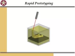
Stereolithography and FDM FIGURE 10.47 Schematic illustration of the stereolithography process. Source: Courtesy of 3D Systems. FIGURE 10.48 (a) Schematic illustration of the fused-deposition modeling process. (b) The FDM Vantage X rapid prototyping machine. Source: Courtesy of Stratasys, Inc.
Support Structures FIGURE 10.49 (a) A part with a protruding section that requires support material. (b) Common support structures used in rapid-prototyping machines. Source: After P.F. Jacobs.
Selective Laser Sintering FIGURE 10.50 Schematic illustration of the selective-laser-sintering process. Source: After C. Deckard and P.F. McClure.
Three-Dimensional Printing FIGURE 10.51 Schematic illustration of the three-dimensional-printing process. Source: After E. Sachs and M. Cima. FIGURE 10.52 (a) Examples of parts produced through three-dimensional printing. Full color parts also are possible, and the colors can be blended throughout the volume. Source: Courtesy ZCorp, Inc.
3D Printing of Metal Parts FIGURE 10.53 The three-dimensional printing process: (a) part build; (b) sintering, and (c) infiltration steps to produce metal parts. Source: Courtesy of the ProMetal Division of Ex One Corporation.
Sprayed Metal Tooling Process FIGURE 10.55 Production of tooling for injection molding by the sprayed-metal tooling process. (a) A pattern and base plate are prepared through a rapid-prototyping operation; (b) a zinc-aluminum alloy is sprayed onto the pattern (See Section 4.5.1); (c) the coated base plate and pattern assembly is placed in a flask and back-filled with aluminum-impregnated epoxy; (d) after curing, the base plate is removed from the finished mold; and (e) a second mold half suitable for injection molding is prepared.
Example: RP Injection Manifold FIGURE 10.56 Rapid prototyped model of an injection-manifold design, produced through stereolithography. Source: 3D Systems.