Measurement Basics II
100 likes | 234 Vues
This guide covers the fundamentals of power supply operation, focusing on current measurement, limiting features, and voltage adjustments. Users will learn how to safely connect a light bulb and LED to the power supply while understanding the implications of the current limit knob. Key safety precautions are outlined, including what to do if the circuit goes into constant current mode. Practical exercises illustrate how to calculate necessary resistor values for an LED and provide knowledge on managing independent and tracked power supplies in various configurations.

Measurement Basics II
E N D
Presentation Transcript
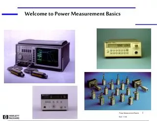
ECE 2100 Measurement Basics II • Power supply: current meter and current limit • Light Bulb and LED! Dr. Len Trombetta
The Power Supply Recall the current limit knob on the power supply… Course Adjust Current Limit Fine Adjust The supply will not provide an infinite current: current will be limited at any particular voltage. The limiting current is adjustable with this knob.
Let’s Have a Little Fun… Note the voltage and current rating on the bulb. What circuit element could we use to model the bulb in an electric circuit schematic? What value would that circuit element have?
Set up… Set the voltage source to 0. Turn the current limit knob fully clockwise (max value). Connect the power supply to the bulb. Slowly increase the voltage until the bulb glows.
Current Measurement 1. Press the V/A button (on whichever supply you are using). With this button pressed in, the display shows current being delivered by the source. 2. Now slowly rotate the current limit knob counter-clockwise. When the current limit goes below the bulb current, the meter goes into “constant current” (CC) mode. The power supply will not deliver more current than the value set by the knob.
Applications… Safety feature: The current limit knob can be set to the max current that should enter the circuit. This will prevent damage to the circuit. Troubleshooting: The smallest value that can be set on the current limit is about 100[mA]. This value is almost certainly larger than any current you will need in the ECE 2100 labs. Therefore, you should not see the CC light go on in ECE 2100. If you do, it probably means your circuit has a “short” somewhere, and that it is drawing more current than it is supposed to.
LED ! LEDs and light bulbs are not part of ECE 2100 ! These are just for fun! Note the polarity! The short leg is connected to the negative terminal. http://en.wikipedia.org/wiki/File:LED,_5mm,_green_(en).svg
A Design Problem… Assume your LED needs 10[mA] to turn on, and has a 0.7 [V] drop across it. Using a dc source of 10 [V], choose a resistor to accomplish this. If your lab kit does not have the required value, which resistor should you choose?
Tracking Power Supplies INDEP/TRACK Out (INDEP): two separate 30 [V] power supplies. In (TRACK): one single 60 [V] power supply. + - Internal connection is made in “TRACK” mode. With supply B COARSE and FINE set fully clockwise, the voltage on A and B will be the same, and will be set by the A knobs. If supply B is not full cw, the two supplies are set independently. In either case, they add.
Tracking Power Supplies In TRACK mode: SER/PAR (series/parallel) Out (SER): power supplies are in series and behave as described last slide. In (PAR): power supplies are connected in parallel and will supply twice the current of one (2 [A] each; 4 [A] total). - + In this mode, supply B will track supply A.