Download
1 / 25
250 likes | 407 Vues
Performance of micro pixel gas chamber in small angle X-ray scattering experiments. Kaori Hattori 1,2 Chihiro Ida 1,2 , Kazuki Ito 2 , Kotaro Fujii 3 , Hidetoshi Kubo 1,2 , Kentaro Miuchi 1,2 , Masaki Takata 2,4,5 , Toru Tanimori 1,2 , Hidehiro Uekusa 3

E N D
Performance of micro pixel gas chamber in small angle X-ray scattering experiments Kaori Hattori1,2 Chihiro Ida1,2, Kazuki Ito2, Kotaro Fujii3, Hidetoshi Kubo1,2, Kentaro Miuchi1,2, Masaki Takata2,4,5, Toru Tanimori1,2, Hidehiro Uekusa3 1Department of Physics, Kyoto University, Japan 2 Structural Materials Science Laboratory, RIKEN Harima Institute/SPring-8 Center, Japan 3 Department of Chemistry and Materials Sicence, Tokyo Institute of Technology, Japan 4 SPring-8/JASRI, Japan 5 Department of Advanced Materials Sciences, Graduate School of Frontier Sciences, The University of Tokyo
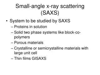
OUTLINE • Development of detectors for structural determination • Requirements for photon counting detectors • Novel photon counting detector, mico-pixel chamber (m-PIC) • Time resolved experiments • Small angle X-ray scattering (SAXS) experiments • Summary IUCr 2008 Osaka, Japan
To provide powerful methods for structural determination • High speed Structural analysis of biological macromolecules (protein) materials radiation within a couple of minutes • High precision • wide dynamic range of>107 • realize high precision measurements • Structural determination of materials with light elements • Time resolved active dynamics photon-induced phase transition record continuum transitionwith a time resolution of sec to sub-msec repeated measurements will provide better time resolution To satisfy these conditions Photon counting detectors with good position resolutions are suitable IUCr 2008 Osaka, Japan
Requirements for two-dimensionalphoton counting detectors 1. Position resolution better than 100 μm 2. Counting rates > 107mm-2, >1000× MWPC (irradiated locally) 3. Large active area of > 150×150 mm2 4. No dead region (ex. junctions) 5. Efficiency difference < 1 % 6. Image distortion < 1 % 7. Operation at room temperature, low power consumption 8. Easy maintenance 9. Low costs A photon counting area detector based on a Micro Pixel Chamber (m-PIC) has realized 4, 6, 7, 8, and 9. 1, 2, and 5 are in progress. 3. A n active area of a m-PIC currently in use is 100×100 mm2 A m-PIC with an active area of 300 ×300 mm2has proved stable runs. Verification experiments at a synchrotron radiation facility are being planned. Readouts without intervals →CRP (continuous rotation photograph) method High gain →sensitivity to low energy X-rays of about 1 keV Anomalous X-ray scattering of sulfur(2.3keV) IUCr 2008 Osaka, Japan
4mm 0.4kV/cm 4mm 1.9kV/cm 400μm Novel gas detector m-PIC (micro-Pixel Chamber) • Mechanism for photon detection • Photoelectric effect in a gas • Emitted electron runs until it loses a kinetic energy • Ionizes atoms • Electron clouds are amplified by a • GEM(gas electron multiplier, F. Sauli, 1997) , andμ-PIC GEM (gas electron multiplier) 70um 140um 100 mm Pixel pitch 400 μm Gas gain m-PIC : 3×10⁴GEM: 3 IUCr 2008 Osaka, Japan
from μ-PIC Outside 256ch per board Printed circuit board μ-PIC pre -amplifier to pre-amplifiers m-PIC is kept in the sealed vessel • The m-PIC is contained in a sealed vessel with a polyimide entrance window of 0.1-mm thickness. • The vessel is filled with Xe-C2H6(70:30) gas. • Stable operation without fresh • gas supply for > 1 month 100 mm Anode 256ch + cathode 256ch Signals from the μ-PIC are sent via the printed circuit boards Sealed vessel IUCr 2008 Osaka, Japan
DAQ Data acquisition (DAQ) ASD Position Encoding Module 100 MHz position, clock (X, T) (Y, T) Detector (m-PIC) Anode 256 ch Digital out 256 ch memory board LVDS out 33 bit Cathode 256 ch VME bus Amplifier Shaper Discriminator (ASD) PC The output charges of the 256+256 channels are parallel pre-amplified, shaped, and discriminated by the ASD chips completely digitized Digital signals are sent to the position encoding module with an internal clock of 100 MHz, allowing the recording of position (X or Y) and the timing T in the memory module Digital out 256 ch (LVDS) IUCr 2008 Osaka, Japan
Advantages of digital readouts • Simple • Low cost • Easy adjustments for detectors with large active area • Fast readout • Characteristic less depends on counting rates • Good counting rate capabilities • m-PIC > 1 MHz charge division < 1 MHz delay line IUCr 2008 Osaka, Japan
Linearity in data acquisition rates Irradiated scattering from a piece of glassy carbon 0.9 Å the best fit of exponential function x1.038 Error:0.7% good linear correlation from 20 cps to 5 Mcps Dynamic range of > 105 No saturation counting rates are limited by a high voltage module IUCr 2008 Osaka, Japan
Performance of m-PIC 2-dimensional imaging gaseous detector pitch 400μm, size 100 mm×100 mm, 300 mm×300 mm 400μm position resolution ~120μm Theoretical limit 10cm Knife edge test Projected image of the test chart edge and the best fit of the error function • Takeda et al., IEEE Transactions on nuclear science, • Vol. 51, No.5, (2004) IUCr 2008 Osaka, Japan X-ray image of test chart and the projected image along 0.5 mm slits
m-PIC as a time-resolved detector CRP (continuous rotation photograph) method Movie of diffraction spots from rotating crystals a crystal rotated by a goniometer timings of incident photons converted to rotation angles of diffraction spots Reducing the measurement time Strong background reduction using a new parameter, rotation angle IUCr 2008 Osaka, Japan
Time Resolved X-ray Crystal Structure Analysis(1999) MSGC(Micro Strip Gas Chamber) Reciprocal lattice Time Movie varying 2q continuously Time resolution of ~ 100 ns for each X-ray Much Information -> quick online analysis IUCr 2008 Osaka, Japan
m-PIC: 3-dimensional image of diffraction spots rotation speed : 4.89 sec/cycle mesurement time : 3716 sec counting rate : 1.05×10⁴ cps Applying the noise reduction using 2q information 3716s 2q<49o Reflections 1556 (331 unique) Rint (internal agreement factor)3.7% Rint of 1% will achieve with ten times the length of accumulation time IUCr 2008 Osaka, Japan Takeda et al.J. Synchrotron Rad. (2005)12, 820-825
Single crystal diffraction and powder diffraction study performed at KEK-PF, Japan BL14A17.5keV μPIC crystal IUCr 2008 Osaka, Japan
Powder diffraction changing temperature (1) KEK Photon Factory 0.7Å Dehydration reaction of a pyromellitic acid hydrate occurs while heat is applying (140℃) hydrate dehydrate 65 sec Change in a diffraction pattern in 7 sec IUCr 2008 Osaka, Japan
Powder diffraction changing temperature (2) The intensity I(2θ, t) is expressed as I = xId(2θ)+ (1-x)Ih (2θ), where Id(2θ), Ih (2θ)is the intensity of the dehydrate, the hydrate, respectively, including a background 0 sec 1.95 sec 3.90 sec 6.50 sec 4.3×10⁴ events / 0.65 sec Time resolution will be expected to about 4 msec with a count rate of 10MHz
μ-PIC Small Angle X-ray Scattering experiments conducted at SPring-8 BL45-XU SAXS station target Camera length 0.6~3.5m beam IUCr 2008 Osaka, Japan
Diffraction pattern of collagen 0.9Å, 1.2 × 10⁵ cps 11 22 Diffraction patterns of collagen with a μ-PIC X-ray imaging system with an accumulation of 106 events, 105 events, and 104 events, respectively. Signal-to-noise ratio in the background of the diffraction pattern was improved
Powder diffraction in SAXS 100 mm • The peaks observed at the holes on the mask moved • < 10 mm when the beam intensity was varied from 8 to 200 kcps • Holes were perpendicularly arranged • The deviation from the perpendicular was <1 degree irradiating a grid mask with scattering from a piece of glassy carbon, 1.5 Å solution scattering frompolystyrenelatex (110 nm, 5 mg / ml), 1.5 Å No spatial distortion was observed IUCr 2008 Osaka, Japan
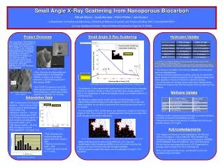
Dynamic Range Polystyrene latex 0.04 weight % solid spheres of 110-nm diameter 1.5 Å exposure time : 154 sec Incident photon flux 1.5 × 10¹¹ photons / s dynamic range Six orders of magnitude CCD: 104 Imaging Plate: 105-6 q-4 106 Close to edge of the detector Low detection efficiency IUCr 2008 Osaka, Japan
Solution Scattering from Apo-Ferritin • Apo-Ferritin • 1.5 Å • exposure time : 436 sec • Solution (m -PIC) • Water (m -PIC) • Solution – water (m-PIC) • R-AXIS (IP) • Incident photon flux • 1.5 × 10¹¹ photons / s • Deviation from IP was • seen in high-q region. • Signal to noise ratio strongly • effects on low-counting • rates region. • Further studies are necessary. IUCr 2008 Osaka, Japan
Detector characteristics Achieved by Gamma-ray camera based on a μ-PIC
Summary • good linear correlation > 105 (20 cps – 5 Mcps) • Position resolution of 120 um • CRP method : Rint (internal agreement factor)3.7% • Time resolved measurements • Image without distortion • Dynamic Range of > 106 IUCr 2008 Osaka, Japan
Photon Counting Detector m-PIC A photonanode : a few signals for ~100 ns cathode : a few signals for ~100 ns coincidence To avoid accidental coincidence Choose between two possibilities: One is correct The other causes accidental coincidence Cut events when another event comes within approximately 20 ns anode cathode 20 ns 20 ns Further improvements are necessary IUCr 2008 Osaka, Japan
300 mm Further Work <schedule> Small-angle neutron scattering at JRR-3, Japan in September Solution scattering experiments at Spring-8, Japan in October Increase detection efficiency dyamic range Confirm consistency under high and low-count rate environments Large m-PIC with an active area of 300×300 mm2 in development IUCr 2008 Osaka, Japan