RTL and Datapaths
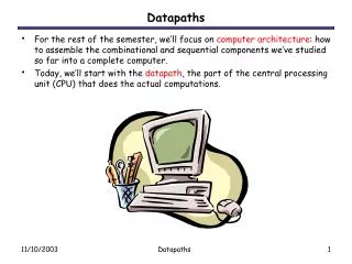
RTL and Datapaths. ECE 0909-443 Y. Tang. Digital System Design. Control unit. Control signals. Datapath. Control input. Status signals. Data outputs. Control outputs. Data inputs. Problem : VLSI circuits contain more gates than a synthesis tool can accommodate.

RTL and Datapaths
E N D
Presentation Transcript
RTL and Datapaths ECE 0909-443 Y. Tang
Digital System Design Control unit Control signals Datapath Control input Status signals Data outputs Control outputs Data inputs • Problem: VLSI circuits contain more gates than a synthesis tool can accommodate • Solution: divide and conquer – partitioning a design • Datapath: perform data-processing operations • Control unit: determine the sequence of operations
Register Transfer Operations 15 8 7 0 R1 R1(H) R1(L) PC IR AR • Register: a group of flip-flops, each of which is capable of storing one bit of information • RTL: The symbolic notation used to describe the micro-operation transfers among registers • Register representation: capital letters (sometimes followed by numerals)
register to register: R2 R1 • Memory to register: M[AR] DR (write) • DR M[AR] (read) • K1: R2 R1 (K1 is any Boolean function that evaluates to 0 or 1) • A comma is used to separate multiple register transfers at the same time Register Transfer Operations • Data Transfer: • Conditional Transfer (if-then): • Basic symbols (including the corresponding VERILOG symbols) -- (p. 344 M & K)
t t+1 clock K1 Register Transfer Operations Any register transfer statement implies that circuits or hardware are available to perform the transfer. K1 clock R1 Control Circuit Load < R2 K1 is activated by the rising edge of a clock pulse at time t. At the next rising edge of the clock at time t+1, since load input K1 is activated, R2’s data is loaded into R1 in parallel.
¬ ¾ ¾ + X K 1 : R 1 R 1 R 2 ¬ ¾ ¾ + + XK 1 : R 1 R 1 R 2 1 Arithmetic Micro-operations • Design one circuit to do both addition and subtraction: • K1 activates an operation and X decides operation type.
Logic Micro-operations b • To clear a bit using an AND since 0 AND b = 0 (b is cleared); 1 AND b = b ( b is conserved) • To set a bit using an OR since 1 OR b = 1 (b is set); 0 OR b = b ( b is conserved) • To complement a bit using a XOR since 1 XOR b = ( b is complemented)
Shift Micro-operations • Logic shift-left/right: R0 shl/shr R0 - incoming bit is assumed to be “0” • Circular shift-left/right: R0 cil/cir R0 - rotate operation without any loss Rn-1 Rn-2 R1 R0 cir R0 Rn-1 Rn-2 R1 R0 cil R0
Multiplexer-based Transfer vs.Bus-based Transfer ¬ ¬ ¬ K 1 : R 0 R 1 , K 1 K 2 : R 0 R 2 , K 1 K 2 K 3 : R 0 R 3 • Question: a register (R0) receives data from different sources (R1,R2 and R3) at different conditions R1 s1 s0 MUX 0 Load R0 R2 1 R3 2
Multiplexer-based Transfer vs.Bus-based Transfer (cont.) ¬ ¬ ¬ K 1 : R 0 R 1 , K 1 K 2 : R 0 R 2 , K 1 K 2 K 3 : R 0 R 3 • Gate-level Modeling • Truth table • Boolean functions for outputs module Control_unit (K1,K2,K3, s0, s1, Load); output s0, s1, Load; input K1,K2,K3; … and (s1, ~K1,~K2); … endmodule
Multiplexer-based Transfer vs.Bus-based Transfer (cont.) • Behavioral Modeling module Control_unit (K1,K2,K3, s0, s1, Load); output s0, s1, Load; input K1,K2,K3; reg s0, s1, Load always @ (K1or K2 or K3) begin if (K1==1) begin s0<=0; s1<=0; Load<=1; end else if (K2==1) begin s0<=1; s1<=0; Load<=1; end else if (K3==1) s0<=0; s1<=1; Load<=1; end endmodule
Multiplexer-based Transfer vs.Bus-based Transfer (cont.) • Exercise: Design the logic to implement the following set of register transfers: C0: R0 <- R1, R2<-R1 C1: R0<-R2 C2: R2<-R0, R1<-R0
Multiplexer-based Transfer vs.Bus-based Transfer (cont.) • Using MUX to transfer data in a system with many data registers will result excessive MUX logic and interconnections - e.g., R0 R1/R2; R1 R0/R2; R2 R1/R0 • Bus: a set of common lines usually driven by selection logic to determine the path between source and destination - MUX-based bus
Multiplexer-based Transfer vs.Bus-based Transfer (cont.) • Simultaneous transfers with different sources in a single clock cycle are impossible, while for the dedicated MUX, any combination of transfers is possible.
Datapaths • Datapath: the datapath representation is usually simplified by the register file and the function unit • Register file: the circuit to store the data to or load the data from the registers, including the selection decoder, the registers and the MUX • Functional Unit: include the arithmetic/logic unit (ALU) and the shifter
ALU is a a combinational circuit with n selection inputs to select up to different operation modes. In the different modes, the data are performed with different micro-operations. ALU • ALU: perform the basic arithmetic and logic micro-operations • Design an ALU with 3 inputs: S0, S1, and S2 • When S2=0, the ALU performs 4 arithmetic operations which are specified by S1S0 • When S2=1, the ALU performs 4 logic operations which are specified by S1S0
n-bit ALU A n N-bit Parallel adder A G B n B input logic B Cin G Cout S0 S0 S1 S1 S2 Cout Arithmetic Circuit Cin n n Y n
= + Y B S B S i 0 1 i i B i Arithmetic Circuit (cont.) • The B input logic can be implemented by n 4 to 1 MUX, and simplified by using K-map.
Logic Circuit • The logic operations are bitwise operations: - Implemented by AND, OR, XOR and NOT gates with a 4 to 1 MUX, bit by bit. - Logic simplification reduces the gate count
The Shifter • The combinational shifter can be implemented by n 3 to 1 MUX for shifting one bit position to the left or right.
Behavioral Modules of the ALU/Shifter module ALU_unit (data_out, c_out, A, B, sel); output [n-1:1] data_out; output c_out; input [n-1:0]A, B; input [3:0] sel1; //including the carry-in bit (i.e., S2, S1, S0, Cin) … always @ (sel1 or A or B) begin case (sel1) 4’b0000: {c_out, data_out}<=0; 4’b0001: {c_out, data_out}<=A+1; … 4’b111x: data_out<=~A; … end endmodule
Behavioral Modules of the ALU/Shifter module Shifter_unit (data_out, data_in, Ir, Il, sel); output [n-1:1] data_out; input Ir, Il; input [1:0] sel2; input [n-1:0] data_in; … always @ (sel2) begin case (sel) 0: data_out<=data_in; 1: data_out<={Ir, data_in[n-1:1]}; … default: data_out<=data_in; … end endmodule
Datapaths Design • Why do we need register file(s)? • A special type of fast memory that permits one or more words to be read and one or more words to be written simultaneously • It is in conjunction with a shared function unit, including ALU and shifter • It provides the data to the inputs of the function unit and stores the result of operation performed on these inputs in the function unit
Datapaths Design • What else do we need besides register file(s), ALU and shifter? • To decide which registers in the register file will provide the data to the inputs of the function unit – two MUX are needed. • To decide either the output of ALU or the one of the shifter to be loaded into the destination register – one MUX is needed • To decide which register in the register file is loaded with the result of an operation in the function unit – one decoder is needed
Datapaths Design • The selection variables for the datapath control the micro-operations executed within the datapath for any clock pulse • The selection (or control) signals are usually concatenated as the control word, whose size depends on the number of control signals
Datapaths Design • The control word for a given microoperation can be derived by specifying the value of the control fields • For example: R1 R2+~R3+1 • the control world is:001_010_011_0_0101_0_1 • Your turn: R4 sl R6 • the control world is: ???