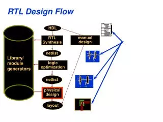
RTL Systems
RTL Systems. References: Introduction to Digital System by Milos Ercegovac,Tomas Lang, Jaime H. Moreno; wiley publisher Digital Design Principles & Practices by J.F.Wakerly, Pearson Education Press, 2007. Introduction. 1. DATA SUBSYSTEM (datapath) AND CONTROL SUBSYSTEM

RTL Systems
E N D
Presentation Transcript
RTL Systems References: Introduction to Digital System by Milos Ercegovac,Tomas Lang, Jaime H. Moreno; wiley publisher Digital Design Principles & Practices by J.F.Wakerly, Pearson Education Press, 2007 DSD,USIT,GGSIPU
Introduction 1. DATA SUBSYSTEM (datapath) AND CONTROL SUBSYSTEM 2. THE STATE OF DATA SUBSYSTEM: • CONTENTS OF A SET OF REGISTERS 3. THE FUNCTION OF THE SYSTEM PERFORMED AS A SEQUENCE OF REGISTER TRANSFERS (in one or more clock cycles) 4. A REGISTER TRANSFER: • A TRANSFORMATION PERFORMED ON A DATA WHILE THE DATA DSD,USIT,GGSIPU
Introduction(cont..) • THE SEQUENCE OF REGISTER TRANSFERS CONTROLLED BY THE CONTROL SUBSYSTEM (a sequential system) • TRANSFERRED FROM ONE REGISTER TO ANOTHER DSD,USIT,GGSIPU
Organization of Systems • TWO FUNCTIONS: • DATA TRANSFORMATIONS :FUNCTIONAL UNITS (operators) - CONTROL OF DATA TRANSFORMATIONS AND THEIR SEQUENCING : CONTROL UNITS • TYPES OF SYSTEMS WITH RESPECT TO FUNCTIONAL UNITS: • NONSHARING SYSTEM • SHARING SYSTEM • UNIMODULE SYSTEM DSD,USIT,GGSIPU
CENTRALIZED CONTROL DSD,USIT,GGSIPU
DeCENTRALIZED CONTROL DSD,USIT,GGSIPU
SemiCENTRALIZED CONTROL DSD,USIT,GGSIPU
Structure of a RTL System DSD,USIT,GGSIPU
Analysis of a RTL System DSD,USIT,GGSIPU
Analysis of a RTL system (cont) DSD,USIT,GGSIPU
Design of Data Subsystem 1. Determine the operators (functional units) -Two operations can be assigned to the same functional unit if they form part of diff erent groups 2. Determine the registers required to store operands, results, and intermediate variables -Two variables can be assigned to the same register if they are active in disjoint time intervals DSD,USIT,GGSIPU
Design of Data Subsystem (cont) 3. Connect the components by datapaths (wires and multiplexers) as required by the transfers in the sequence 4. DETERMINE THE CONTROL SIGNALS AND CONDITIONS required by the sequence 5. DESCRIBE THE STRUCTURE OF THE DATA SECTION by a logic diagram, a net list, or a VHDLstructural description DSD,USIT,GGSIPU
Data SubSystem i) STORAGE MODULES ii) FUNCTIONAL MODULES (operators) iii) DATAPATHS (switches and wires) iv) CONTROL POINTS v) CONDITION POINTS DSD,USIT,GGSIPU
Storage Modules • INDIVIDUAL REGISTERS, with separate connections and controls; • ARRAYS OF REGISTERS, sharing connections and controls; • REGISTER FILE • RANDOM-ACCESS MEMORY (RAM) • COMBINATION OF INDIVIDUAL REGISTERS AND ARRAYS OF REGISTERS. DSD,USIT,GGSIPU
Register File DSD,USIT,GGSIPU
Entity Declaration of Register File ENTITY reg_file IS GENERIC(n: NATURAL:=16; -- word width p: NATURAL:= 8; -- register file size k: NATURAL:= 3); -- bits in address vector PORT (X : IN UNSIGNED(n-1 DOWNTO 0); -- input WA : IN UNSIGNED(k-1 DOWNTO 0); -- write address RAl : IN UNSIGNED(k-1 DOWNTO 0); -- read address (left) RAr : IN UNSIGNED(k-1 DOWNTO 0); -- read address (right) Zl,Zr: OUT UNSIGNED(n-1 DOWNTO 0); -- output (left,right) Wr : IN BIT; -- write control signal clk : IN BIT); -- clock END reg_file; DSD,USIT,GGSIPU
Behavioral Description of Register File ARCHITECTURE behavioral OF reg_file IS SUBTYPE WordT IS UNSIGNED(n-1 DOWNTO 0); TYPE StorageT IS ARRAY(0 TO p-1) OF WordT; SIGNAL RF: StorageT; -- reg. file contents BEGIN PROCESS (clk) -- state transition BEGIN IF (clk'EVENT AND clk = '1') AND (Wr = '1') THEN RF(CONV_INTEGER(WA)) <= X; -- write operation END IF; END PROCESS; PROCESS (RAl,RAr,RF) BEGIN -- output function Zl <= RF(CONV_INTEGER(RAl)); Zr <= RF(CONV_INTEGER(RAr)); END PROCESS; END behavioral; DSD,USIT,GGSIPU
Description of RAM Design DSD,USIT,GGSIPU
Entity Declaration of RAM ENTITY ram IS GENERIC(n: NATURAL:= 16; -- RAM word width p: NATURAL:=256; -- RAM size k: NATURAL:= 8); -- bits in address vector PORT (X : IN UNSIGNED(n-1 DOWNTO 0); -- input bit-vector A : IN UNSIGNED(k-1 DOWNTO 0); -- address bit-vector Z : OUT UNSIGNED(n-1 DOWNTO 0); -- output bit-vector Rd,Wr: IN BIT; -- control signals Clk : IN BIT); -- clock signal END ram; DSD,USIT,GGSIPU
RAM Description ARCHITECTURE behavioral OF ram IS SUBTYPE WordT IS UNSIGNED(n-1 DOWNTO 0); TYPE StorageT IS ARRAY(0 TO p-1) OF WordT; SIGNAL Memory: StorageT; -- RAM state BEGIN PROCESS (Clk) -- state transition BEGIN IF (Clk'EVENT AND Clk = '1') AND (Wr = '1') THEN Memory(CONV_INTEGER(A)) <= X; -- write operation END IF; END PROCESS; PROCESS (Rd,Memory) -- output function BEGIN IF (Rd = '1') THEN -- read operation Z <= Memory(CONV_INTEGER(A)); END IF; END PROCESS; END behavioral; DSD,USIT,GGSIPU
Functional Modules DSD,USIT,GGSIPU
Data Path • WIDTH OF DATAPATH • PARALLEL OR SERIAL • UNIDIRECTIONAL OR BIDIRECTIONAL • DEDICATED OR SHARED (bus) • DIRECT OR INDIRECT DSD,USIT,GGSIPU
Figure 14.5: EXAMPLES OF DATAPATHS: a) unidirectional dedicated datapath (serial); b) bidirectional dedicated datapath (parallel);c) shared datapath (bus). DSD,USIT,GGSIPU
Generalized behavioral Description DSD,USIT,GGSIPU
Interface between Data and control sub system DSD,USIT,GGSIPU
Design of control sub system 1. DETERMINE THE REGISTER-TRANSFER SEQUENCE 2. ASSIGN ONE STATE TO EACH RT-group 3. DETERMINE STATE-TRANSITION AND OUTPUT FUNCTIONS 4. IMPLEMENT THE CORRESPONDING SEQUENTIAL SYSTEM DSD,USIT,GGSIPU
CONTROL SUBSYSTEM • INPUTS: control inputs to the system and conditions from the data subsystem • OUTPUTS: control signals • ONE STATE PER STATEMENT IN REGISTER-TRANSFER SEQUENCE • TRANSITION FUNCTION CORRESPONDS TO SEQUENCING • OUTPUT FOR EACH STATE CORRESPONDS TO • CONTROL SIGNALS DSD,USIT,GGSIPU
State Assignment • UNCONDITIONAL: only one successor to a state • CONDITIONAL: several possible successors , depending on the value of a condition DSD,USIT,GGSIPU
Moore vs Mealy FSM DSD,USIT,GGSIPU
Design of Multiplier (example) DSD,USIT,GGSIPU
Entity Declaration of Multiplier DSD,USIT,GGSIPU
Control system of Multiplier DSD,USIT,GGSIPU
Control Sub-system (description) ENTITY multctrl IS GENERIC(n: NATURAL := 16); -- number of bits PORT (start : IN BIT; -- control input ldX,ldY,ldZ: OUT BIT; -- control signals shY, clrZ : OUT BIT; -- control signals done : OUT BIT; -- control output clk : IN BIT); END multctrl; DSD,USIT,GGSIPU
Behavior Description ARCHITECTURE behavioral OF multctrl IS TYPE stateT IS (idle,setup,active); SIGNAL state : stateT:= idle; SIGNAL count : NATURAL RANGE 0 TO n-1; BEGIN PROCESS (clk) -- transition function BEGIN IF (clk'EVENT AND clk = '1') THEN CASE state IS WHEN idle => IF (start = '1') THEN state <= setup; ELSE state <= idle; END IF; WHEN setup => state <= active; count <= 0; WHEN active => IF (count = (n-1)) THEN count <= 0; state <= idle ; ELSE count <= count+1; state <= active; END IF; END CASE; END IF; END PROCESS; DSD,USIT,GGSIPU
Behavioral description (cont..) PROCESS (state,count) -- output function VARIABLE controls: BitVector(5 DOWNTO 0); -- code = (ldX,ldY,ldZ,shY,clrZ) BEGIN CASE state IS WHEN idle => controls := "100000"; WHEN setup => controls := "011001"; WHEN active => controls := "000110"; END CASE; done <= controls(5); ldX <= controls(4); ldY <= controls(3); ldZ <= controls(2); shY <= controls(1); clrZ<= controls(0); END PROCESS; END behavioral; DSD,USIT,GGSIPU